00195166-0402_SM_D4_EN.pdf - 第115页
Service W ork Tools Modular Co nveyor Service Manual SIPLACE D4 115 4.4 Modular Conveyor See also: J 2.1 Safety Instructions [ J 13] 4.4.1 T ools Set of open-en ded wrenches Set of Allen keys If needed:Circli p p…

Service Work
Component Handling Cutter
114 Service Manual SIPLACE D4
4.3.2.14 Final Steps
X Make certain that each of the cables running out of the left and right of the control board box is again
fastened to the fixing pedestal with cable tie.
Make sure that there is no strain on the cables.
X If necessary, check the gap between the leading edge of the tape deflector and the empty-tape
baffle, inside.
X Where applicable, mount the tape chute into the machine.
X From below, mount the stop buffer assembly on the machine base (two M8 socket hex head cap
screws on left and right).
X If the nozzle changer is removed, stop the nozzle changer over the installation position and and
make the electrical and pneumatic connections.
X Fit the nozzle changer.
X Turn the compressed air back on at the main switch of the compressed air unit.
X Move the changeover table back into the machine and connect it.
X Calibrate the nozzle changer.
X Load the SITEST program and actuate the cutting strokes (see Operating Manual "SITEST
Program").
X If the nozzle changer was removed:
X Use the SITEST program to calculate the position of the nozzle changer.
X Exit the SITEST program.
X Perform a visual check to make certain that all empty-tape ends are correctly guided downward in
the empty-tape duct.
See also:
J
Tightening Torques for Cutter Screws [
J
87]
J
6.4.3 Check the gap between the empty-tape baffle, inside and the leading edge of the tape deflector.
[
J
241]
CAUTION:
Tighten the screws to the correct torque.
DANGER:
X The SITEST program may only be started by personnel who have been trained in its use by
ASM AS and are therefore authorized to do so.
X When the SITEST program is used, additional, higher risk of an accident exists aside from
the generally higher danger posed by the blades of the cutter.
X The cutter and the empty-tape duct have to be completely assembled at all times.
X The changeover table must be moved into the machine and connected correctly.
X Never move your hand near the cutter, neither from below nor from above (via the empty-tape
duct), not even to resolve a problem.
X When the SITEST program is running, you must always make certain that there is no 2nd
person at the machine, i.e., that no 2nd person can trigger the cutting process or is within the
operating area of the cutter.
X Secure the area of the cutters appropriately to prevent unauthorized access.
X The key switch remains locked (= normal mode = position "0").
X One-way restrictors are not to be set on the machine. This is only permitted at the factory.

Service Work
Tools Modular Conveyor
Service Manual SIPLACE D4
115
4.4 Modular Conveyor
See also:
J
2.1 Safety Instructions [
J
13]
4.4.1 Tools
Set of open-ended wrenches
Set of Allen keys
If needed:Circlip pliers
See also:
J
5 Measuring Equipment and Tools [
J
201]
WARNING: Nonobservance of these safety instructions may cause injury to personnel
and damage to the machine!
The service work described in this manual may only be performed by specially trained service
technicians, with appropriate qualifications and expertise.
X Please observe the safety instructions in the Operating Manual for all service work!
Service Work
Modular Conveyor Replacing the Complete Drive Unit [00359284]
116 Service Manual SIPLACE D4
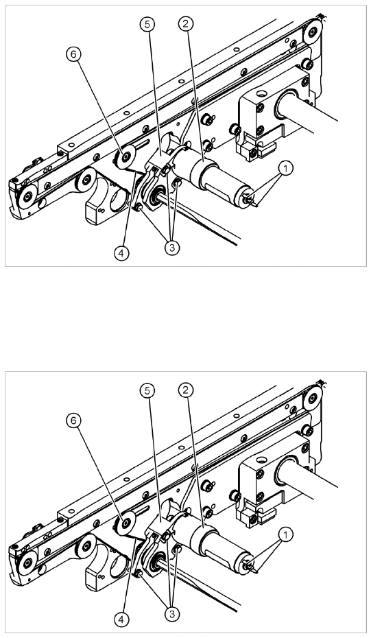
4.4.2 Replacing the Complete Drive Unit [00359284]
Overview
Removal
Legend
1. Cable connections
2. Heat-shrinkable sleeve
3. Fastening screws
4. Conveyor toothed belt
5. Motor mount
6. Deflection pulley with slot
The DC geared motors, including the motor
mounts of all 5 conveyor areas, are of like
construction. Please bear in mind the following
differences during assembly and disassembly:
The motor mount is installed at an angle
(tilted), according to the requirements of the
installation site.
X Move the conveyor system apart until the
motor fixture screws (3) are accessible. This
may differ according to the conveyor type and
area.
X Move the Y gantries into the area outside the
PCB conveyor.
X Switch off the machine and secure it to prevent
unauthorized reactivation.
X Mark the polarity (+ / -) of the cable
connections (1) - important for the direction of
rotation!
X Disconnect the cable shoes from the motor
terminals (1).