00195166-0402_SM_D4_EN.pdf - 第116页
Service Work Modular Conveyor Replacing the Complete Drive Unit [00359284] 116 Serv ice Manual SIPLACE D4 4.4.2 Replacing the Comple te Drive Unit [00359284] Overview Removal Legend 1. Cable conn ections 2. Heat-shrinkab…

Service Work
Tools Modular Conveyor
Service Manual SIPLACE D4
115
4.4 Modular Conveyor
See also:
J
2.1 Safety Instructions [
J
13]
4.4.1 Tools
Set of open-ended wrenches
Set of Allen keys
If needed:Circlip pliers
See also:
J
5 Measuring Equipment and Tools [
J
201]
WARNING: Nonobservance of these safety instructions may cause injury to personnel
and damage to the machine!
The service work described in this manual may only be performed by specially trained service
technicians, with appropriate qualifications and expertise.
X Please observe the safety instructions in the Operating Manual for all service work!
Service Work
Modular Conveyor Replacing the Complete Drive Unit [00359284]
116 Service Manual SIPLACE D4
4.4.2 Replacing the Complete Drive Unit [00359284]
Overview
Removal
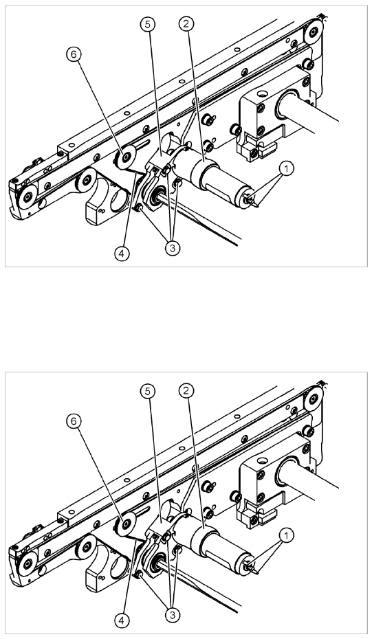
Legend
1. Cable connections
2. Heat-shrinkable sleeve
3. Fastening screws
4. Conveyor toothed belt
5. Motor mount
6. Deflection pulley with slot
The DC geared motors, including the motor
mounts of all 5 conveyor areas, are of like
construction. Please bear in mind the following
differences during assembly and disassembly:
The motor mount is installed at an angle
(tilted), according to the requirements of the
installation site.
X Move the conveyor system apart until the
motor fixture screws (3) are accessible. This
may differ according to the conveyor type and
area.
X Move the Y gantries into the area outside the
PCB conveyor.
X Switch off the machine and secure it to prevent
unauthorized reactivation.
X Mark the polarity (+ / -) of the cable
connections (1) - important for the direction of
rotation!
X Disconnect the cable shoes from the motor
terminals (1).
Service Work
Replacing the Complete Drive Unit [00359284] Modular Conveyor
Service Manual SIPLACE D4
117
Installation
See also:
J
6.5.1 Adjusting the Tension of the Conveyor Toothed Belt [
J
242]
X Strip the heat-shrinkable sleeve, (2) used to
fasten the connection cable, from the
circumference of the DC geared motor.
NOTE:
If necessary, loosen the deflection
pulley at the slot (6). This will make it
easier to unthread the motor mount.
Then correct the belt tension.
X Remove the 3 screws (3) holding the motor
mount in place (5).
X Push the hexagonal shaft back and carefully
remove the motor mount (5). At the same time,
carefully unthread the conveyor toothed belt.
ATTENTION: Do not damage the
toothed belt!
The toothed belts must not be
stretched or kinked!
NOTE:
The way in which the conveyor toothed belt is run around the belt guide depends upon the
transport area concerned. Please observe this belt guidance during assembly.
NOTE:
If you have discovered a break in the motor cable during a continuity check, the motor cable
must be unthreaded as far as the conversion board of the conveyor side (see circuit diagrams
of the same name) and unplugged at the corresponding point. This might be somewhat
complicated depending on the routing of cables inside the machine base.
X You may wish to contact SIPLACE Service regarding this work.
X Fit the new drive unit in the reverse order.
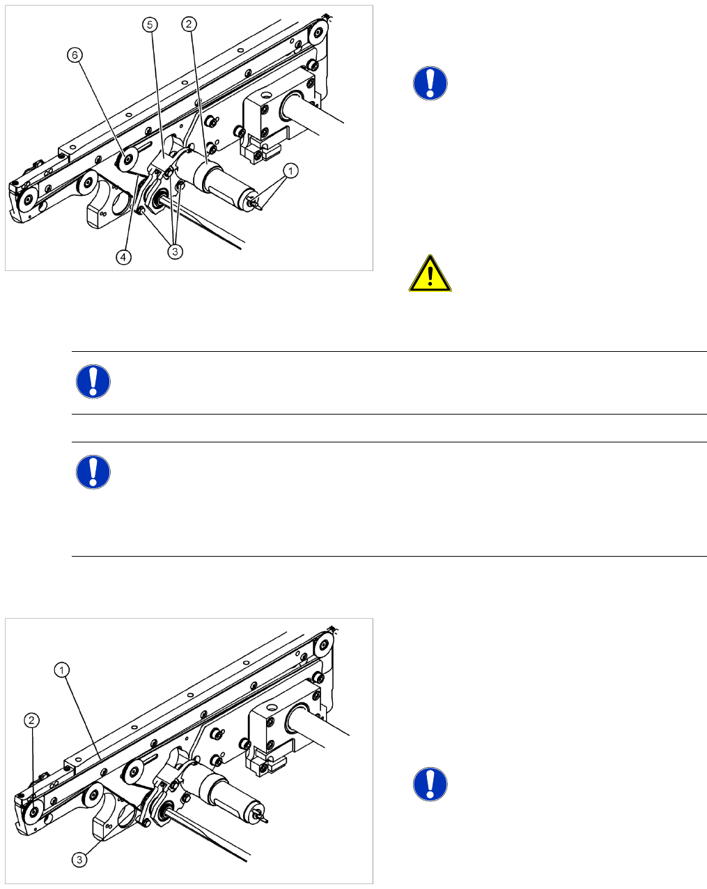
X Please check:
The entire width of the conveyor toothed belt
(1) must engage at all toothed disks (2) and be
run around the belt guide (3).
X Perform the Final steps including function
test.
NOTE:
After the new drive has been installed,
you must make certain that the
direction of rotation and the conveyor
speed (motor voltage) are correct.
After reconnecting the geared motor,
you only need to check the direction of
rotation.