00195166-0402_SM_D4_EN.pdf - 第125页
Service W ork Replacing the Lifting Table Unit [00358653] Modular Co nveyor Service Manual SIPLACE D4 125 Removal Installation See also: J 6.5.11.1 Adjusting the Spee d of th e Lifting Table (from SW 602) [ J 257] Lege…
Service Work
Modular Conveyor Replacing the Lifting Table Unit [00358653]
124 Service Manual SIPLACE D4
4.4.5.1 Adjusting the Tension of the Conveyor Toothed Belt
4.4.6 Replacing the Lifting Table Unit [00358653]
Parts
Lifting table unit for single conveyors [00358653-xx]
Lifting table unit for dual conveyors [00358654-xx]
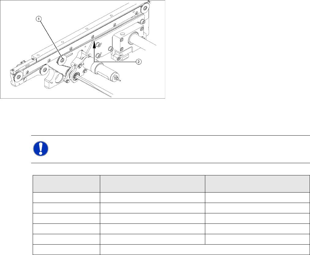
Legend
1. Deflection pulley with slot
2. Measuring point of the belt tension measuring
device (strand center )
X The deflection pulley, around which the
conveyor toothed belt is run, is fastened at a
slot. The tension of the conveyor toothed belt
can be adjusted via this deflection pulley.
X Position the measuring point of the belt
tension device at the strand center (i.e. the
longest distance between the two deflection
pulleys) of the conveyor toothed belt.
X Set the tension of the drive toothed belt
according to the following values.
NOTE:
The tension frequencies per area may vary according to the different belt guides. The belt
tension always remains the same.
Belt tension For conveyor lane 1
(single and dual conveyor)
Conveyor lane 2
(dual conveyor)
Input conveyor 90 Hz +/- 9 Hz 90 Hz +/- 9 Hz
Placement area 1 72 Hz +/- 7 Hz 72 Hz +/- 7 Hz
Intermediate conveyor 144 Hz +/- 14 Hz 115 Hz +/- 12 Hz
Placement area 2 90 Hz +/- 97 Hz 90 Hz +/- 9 Hz
Output conveyor 90 Hz +/- 9 Hz 90 Hz +/- 9 Hz
Width adjustment 24 Hz +/- 2 Hz
Service Work
Replacing the Lifting Table Unit [00358653] Modular Conveyor
Service Manual SIPLACE D4
125
Removal
Installation
See also:
J
6.5.11.1 Adjusting the Speed of the Lifting Table (from SW 602) [
J
257]
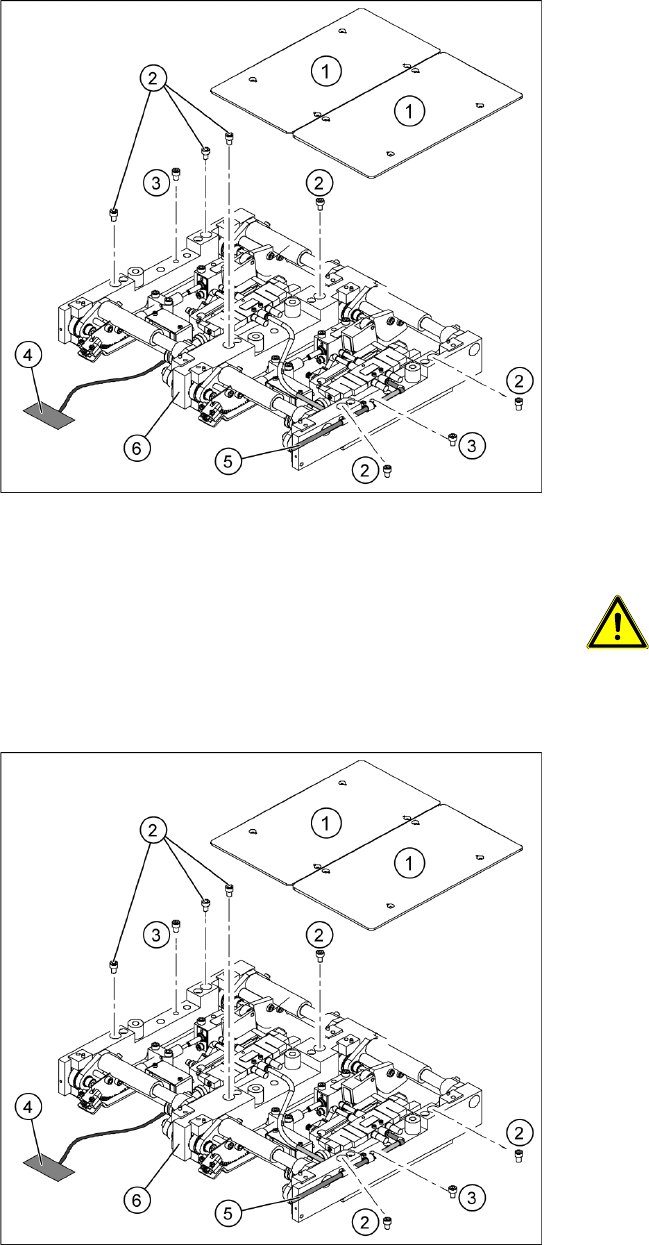
Legend
1. Fastening screws for the lifting table plate
2. 6 x fastening screws for the lifting table
(M8 x 100)
3. 2 x fastening screws for the lifting table
(M6 x 50)
X Move the PCB conveyor to a suitable position
from which you have best access to the lifting
table unit.
X Loosen the screw fastening the lifting table
plate (1) and remove the lifting table plate from
the lifting table unit.
X Loosen the screws (2) and (3) fastening the
lifting table unit.
X Remove the cover on the conveyor conversion
board and unplug the connection cable (4)
from the lifting table unit.
X Unplug the compressed air connection (5).
X Carefully lift the lifting table (6) off the locating
pins.
ATTENTION: Heavy machine part!
When removing the lifting table,
remember it is heavy (17.5 kg).
X Lift the lifting table unit (6) into the machine
and position it on the locating pins.
X Screw in the fastening screws (2) and (3).
X Reconnect to the electrical (4) and
compressed air (5) systems.
X Check the lifting table speed and the
functionality of the PCB clamping device,
without the lifting table plate.
X Adjust the speed of the lifting table.
X Carefully place the lifting table plate (1) onto
the lifting table unit and tighten the fastening
screws diagonally, so that the lifting table plate
does not stick.
X Check the lifting table speed once the lifting
table plate has been installed.
Service Work
Modular Conveyor Replacing the Lifting Table Solenoid Valve [00358663]
126 Service Manual SIPLACE D4
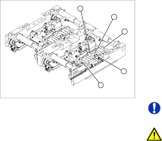
4.4.7 Replacing the Lifting Table Solenoid Valve [00358663]
Removal/Installation
Legend
1. Solenoid valve with 2 x fastening screws
2. Connection plug
3. Compressed air connections
X Move the PCB conveyor to the position which
gives you best access to the lifting table.
X Move the Y gantries into the area outside the
PCB conveyor.
X Switch off the machine and secure it to prevent
unauthorized reactivation.
X Loosen the screw fastening the lifting table
plate and remove the lifting table plate from the
lifting table unit.
NOTE:
You may wish to completely dismantle
the lifting table, to give you better
access to the solenoid valves.
ATTENTION: Heavy machine part!
When removing the lifting table,
remember it is heavy (17.5 kg).
X Switch off the compressed air supply and
release the air at the pneumatic unit filter.
X Loosen the screws fastening the connection
plug and then unplug it.
X Remove the compressed air connections.
X Fit the new solenoid valve and reconnect the
electrical and compressed air systems.
X Fit the complete lifting table into the machine
again.
X Check the speed of the lifting table and correct
where necessary.
3
2
1
3
2