00195166-0402_SM_D4_EN.pdf - 第130页
Service Work Modular Conveyor Replacing the Lifting Tabl e Stabilizer (Stabilizer Unit) [00358684-xx] 130 Serv ice Manual SIPLACE D4 Removal Installation and adjustment X Move the PCB conveyor to the position which gives…
Service Work
Replacing the Lifting Table Stabilizer (Stabilizer Unit) [00358684-xx] Mod ular Conveyor
Service Manual SIPLACE D4
129
Installation
4.4.10 Replacing the Lifting Table Stabilizer (Stabilizer Unit) [00358684-xx]
Overview
Tools and equipment required
Torque wrench with plug-in ratchet [00386175-xx]
Plug-in wrench 16 mm [00386177-xx]
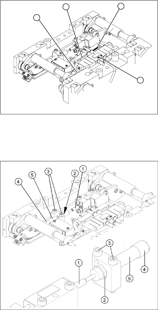
X Insert and fasten the new lifting table cylinder
(2) and install the piston rod (3).
X Move the lifting table by hand to its end
position.
X Switch the machine on.
X Push the end position proximity switch (1) into
the guide rail until the LED lights up.
X Fix this position with the grub screw.
X Install the solenoid valve (4) and the lifting
table plate.
X Check the speed of the lifting table and correct
where necessary.
4
1
3
2
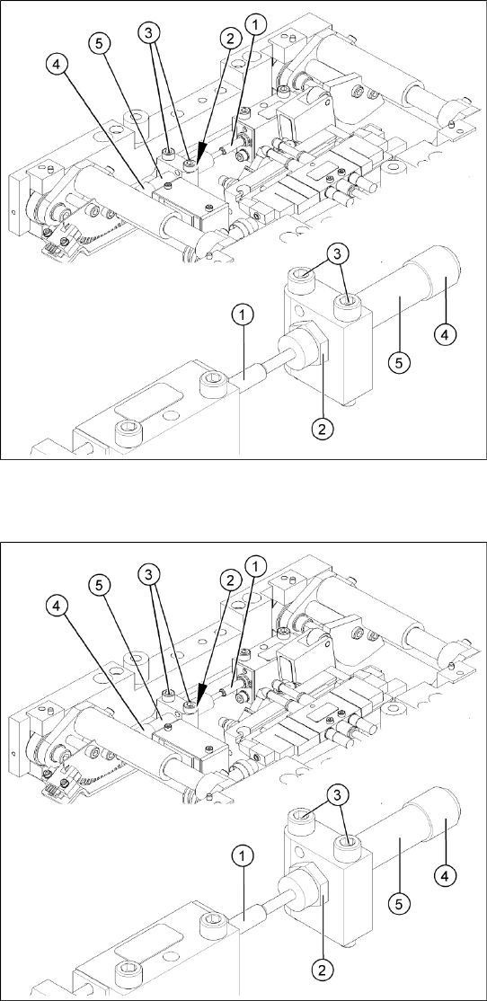
Legend
1. Actuator
2. Locknut
3. Fastening screws
4. Handle
5. Stabilizer [00358684-xx]
The stabilizer enables the lifting table to be moved
gently upwards. It prevents the PCBs from being
clamped in with too much impact.
The stabilizer consists of the shock absorber
[00367737-xx] and the damping block [00367782-
xx].
Service Work
Modular Conveyor Replacing the Lifting Table Stabilizer (Stabilizer Unit) [00358684-xx]
130 Service Manual SIPLACE D4
Removal
Installation and adjustment
X Move the PCB conveyor to the position which
gives you best access to the lifting table.
X Move the Y gantries into the area outside the
PCB conveyor.
X Switch off the machine and secure it to prevent
unauthorized reactivation.
X Loosen the screws fastening the lifting table
plate and remove the lifting table plate from the
lifting table unit.
X Loosen the two screws (3) holding the
stabilizer (5).
X Undo the locknut (2) and take the stabilizer by
its handle (4), twisting it out of the mounting
block.
X Insert and twist the new stabilizer (5) until the
plunger just touches the actuator (1), so that
the lifting table can be gently moved upwards.
X Use a torque wrench:
Secure this position with the locknut (2)
tightened to 8Nm.
X Check whether the stabilizer has been fixed
onto the mounting block with the locknut and
that the stabilizer plunger has a gap of approx.
0.1 mm to the actuator (gap in untriggered
mode). In this default setting, the lifting table
should move up gently.
X If this is not the case, loosen the locknut and
turn the stabilizer approx. one rotation into the
mounting block.
X Fit the lifting table plate.
X Start SITEST and move the lifting table up.
X The lifting table should move up gently i.e. you
should not hear the PCB clamping device
audibly locking into place and no clamping
device error messages should be issued.
X Check the speed of the lifting table cylinder
and correct where necessary.
Service Work
Replacing the Stepping Motor of the Width Adjustment System [00367174] Modular Conveyor
Service Manual SIPLACE D4
131
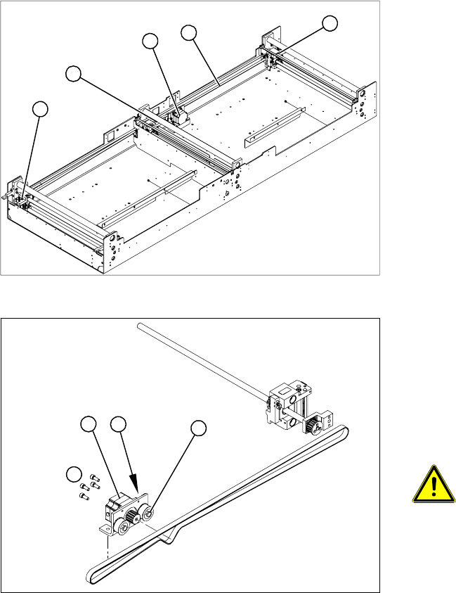
4.4.11 Replacing the Stepping Motor of the Width Adjustment System [00367174]
Overview
Legend
1. Width adjustment stepping motor
2. Toothed belt for the drive
3. Adjustment units 1, 2 and 3
3
3
1
3
2
Legend
1. Loosening the eccentric axle on the deflection
pulley
2. Locknut on the eccentric axle
3. Fastening screws for stepping motor
4. Stepping motor
ATTENTION: Do not damage the
toothed belt!
During the following removal and
installation of the motor, the toothed
belt for the width adjustment drive must
not be stretched or kinked!
X Move the PCB conveyor to the position which
gives you best access to the stepping motor of
the width adjustment system.
X Move the Y gantries into the area outside the
PCB conveyor.
X Switch off the machine and secure it to prevent
unauthorized reactivation.
4
1
3
2