00195166-0402_SM_D4_EN.pdf - 第134页
Service Work Modular Conveyor Replacing the Limit Switch for the End Position Width Adjustment System 134 Serv ice Manual SIPLACE D4 Removal/Installation NOTE: The limit switches are pr eassembl ed and include cables. X …
Service Work
Replacing the Limit Switch for the End Position Width Adjustment System [00365108-xx] Modular Conveyor
Service Manual SIPLACE D4
133
4.4.12 Replacing the Limit Switch for the End Position Width Adjustment System
[00365108-xx]
Parts
Limit switch on the assembly tray [00365002-xx]
Limit switch for width adjustment 1 [00365108-xx]
Limit switch for width adjustment 2 [00365109-xx]
Limit switch for width adjustment - on the conveyor side [00362345-xx]
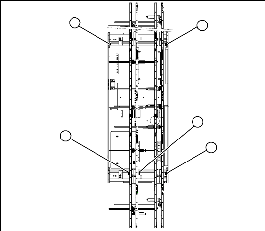
Overview
Legend
1. Limit switch 1 for width adjustment system of
the adjustment unit
2. Limit switch for width adjustment system (for
side)
3. Limit switch for assembly tray (for side)
4. Limit switch 2 for width adjustment system of
the adjustment unit
Limit switch on the input conveyor:
In the vicinity of the input conveyor there are 4 limit
switches under the conveyor sides. The limit
switch is designed to prevent the conveyor sides
hitting one another or the conveyor base.
Limit switch on the output conveyor:
There are 2 limit switches for the adjustment unit
in the vicinity of the output conveyors. They serve
to secure the transport area and to initialize the
adjustment unit during width adjustment.
2
1
4
3
2
Service Work
Modular Conveyor Replacing the Limit Switch for the End Position Width Adjustment System
134 Service Manual SIPLACE D4
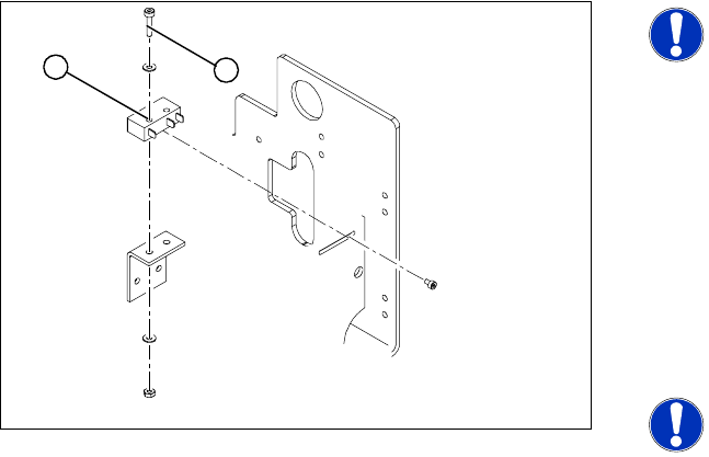
Removal/Installation
NOTE:
The limit switches are preassembled
and include cables.
X However, if the limit switch itself is
faulty, the wiring can be unsoldered/
soldered right at the switch in
question.
X Unsolder the connection wires on the faulty
limit switch (1).
X Loosen and remove the two screws (2)
fastening the defective limit switch.
X Fit the new limit switch and re-solder the
connection wires in the correct allocation.
NOTE:
If you have discovered a break in the
connection cable during a continuity
check, this cable must be unthreaded
as far as the conversion board of the
assembly tray and unplugged there.
This might be somewhat complicated
depending on the routing of cables
inside the machine base.
X You may wish to contact SIPLACE
Se
rvice regarding this
work.
Checking t
he position of the limit switch:
X Check the minimum and maximum width of
the relevant machine type and the parallelism
of the conveyor sides.
1
2
Service Work
Replacing the Solenoid Valve for the Adjustment Unit [00369014-xx] Modular Conveyor
Service Manual SIPLACE D4
135
4.4.13 Replacing the Solenoid Valve for the Adjustment Unit [00369014-xx]
Parts
Solenoid valve for adjustment unit 1 [00363779-xx]
Solenoid valve for adjustment unit 2 [00363780-xx]
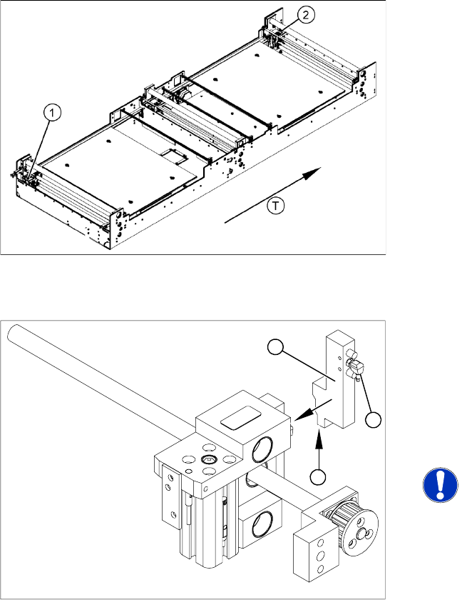
Overview
Removal/Installation
Legend
1. Adjustment unit 1
2. Adjustment unit 2
T = transport direction
X Move the PCB conveyor to the position which
gives you best access to the adjustment
system.
X Move the Y gantries into the area outside the
PCB conveyor.
X Switch off the machine and secure it to prevent
unauthorized reactivation.
X Switch off the compressed air supply.
X Remove the compressed air connections (2).
X Loosen the two fastening screws and remove
the solenoid valve (3) from the short-stroke
cylinder.
X Unthread the connection cable (1) as far as the
relevant assembly tray conversion board and
unplug.
NOTE:
This might be somewhat complicated
depending on the routing of cables
inside the machine base.
X You may wish to contact SIPLACE
Servic
e regarding this
work.
X Fit the ne
w solenoid valve (3) and reconnect
the system to the electrical (1) and
compressed air (2) supplies.
1
3
2