00195166-0402_SM_D4_EN.pdf - 第136页
Service Work Modular Conveyor Replacing the Cylinder Sw itch for the Adjustment U nit [00369016] 136 Serv ice Manual SIPLACE D4 4.4.14 Replacing the Cylinder Switch for the Adjustment Unit [00369016] Parts Cylinder swi…
Service Work
Replacing the Solenoid Valve for the Adjustment Unit [00369014-xx] Modular Conveyor
Service Manual SIPLACE D4
135
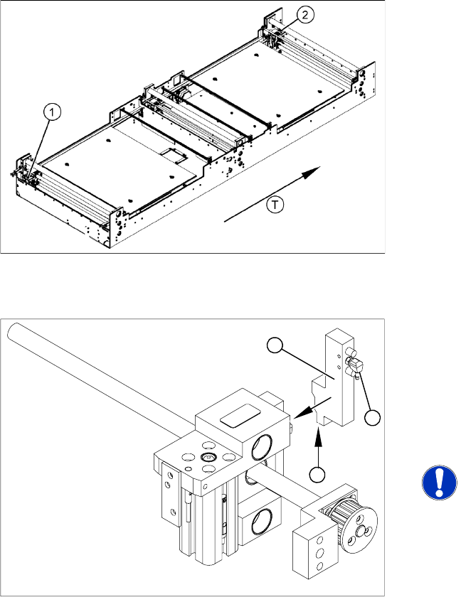
4.4.13 Replacing the Solenoid Valve for the Adjustment Unit [00369014-xx]
Parts
Solenoid valve for adjustment unit 1 [00363779-xx]
Solenoid valve for adjustment unit 2 [00363780-xx]
Overview
Removal/Installation
Legend
1. Adjustment unit 1
2. Adjustment unit 2
T = transport direction
X Move the PCB conveyor to the position which
gives you best access to the adjustment
system.
X Move the Y gantries into the area outside the
PCB conveyor.
X Switch off the machine and secure it to prevent
unauthorized reactivation.
X Switch off the compressed air supply.
X Remove the compressed air connections (2).
X Loosen the two fastening screws and remove
the solenoid valve (3) from the short-stroke
cylinder.
X Unthread the connection cable (1) as far as the
relevant assembly tray conversion board and
unplug.
NOTE:
This might be somewhat complicated
depending on the routing of cables
inside the machine base.
X You may wish to contact SIPLACE
Servic
e regarding this
work.
X Fit the ne
w solenoid valve (3) and reconnect
the system to the electrical (1) and
compressed air (2) supplies.
1
3
2
Service Work
Modular Conveyor Replacing the Cylinder Switch for the Adjustment Unit [00369016]
136 Service Manual SIPLACE D4
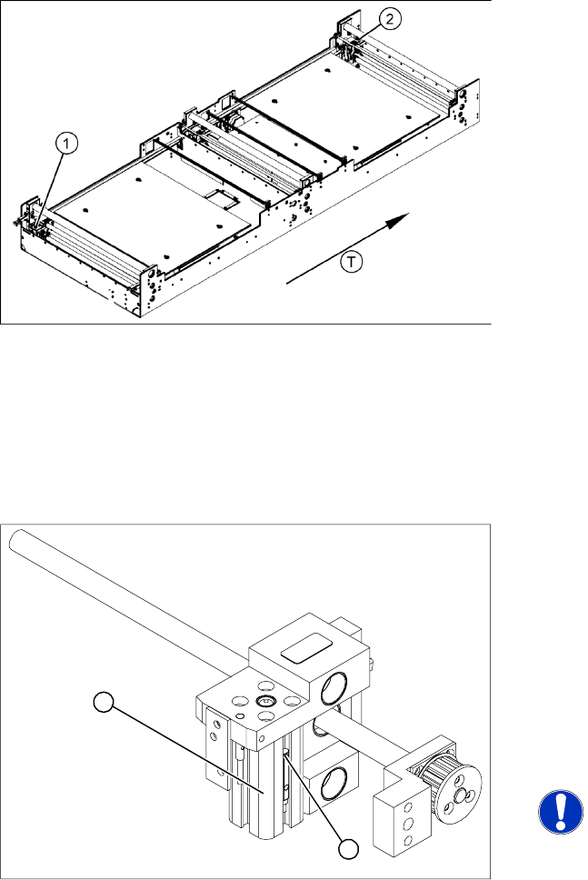
4.4.14 Replacing the Cylinder Switch for the Adjustment Unit [00369016]
Parts
Cylinder switch for width adjustment 1 [00363267-xx]
Cylinder switch for width adjustment 2 [00363291-xx]
Overview
X Move the PCB conveyor to the position which gives you best access to the adjustment system.
X Move the Y gantries into the area outside the PCB conveyor.
X Switch off the machine and secure it to prevent unauthorized reactivation.
X Switch off the compressed air supply.
Removal/Installation
The cylinder switch on the adjustment unit cylinder
should operate when the adjustment unit pin is
pushed out by the pneumatic cylinder and
therefore connected to the conveyor side. This
signal enables the width adjustment motor.
Legend
1. Adjustment unit 1
2. Adjustment unit 2
T = transport direction
X Loosen the grub screw at the cylinder switch
(1) and push the cylinder switch out of the
adjustment unit guide rail (2).
X Unthread the connection cable as far as the
conversion board of the assembly tray.
X Run the connection cable of the new cylinder
switch (2).
X Insert the new cylinder switch into the guide
rail.
X Switch the machine on.
NOTE:
The width adjustment system cylinder
switch is set in engaged mode.
X Move the width adjustment system until the
cylinder switch switches - LED (H36/H37)
lights up.
X Engage the cylinder - i.e. the cylinders are
moved to the upper limit by the controls.
X Set the cylinder switch so that the LED lights
up when it is in engaged mode.
X Fix the position of the cylinder switch (2) with
the grub screw.
2
1
Service Work
Replacing the Proximity Switch for the Adjustment System [00363268] Modular Conveyor
Service Manual SIPLACE D4
137
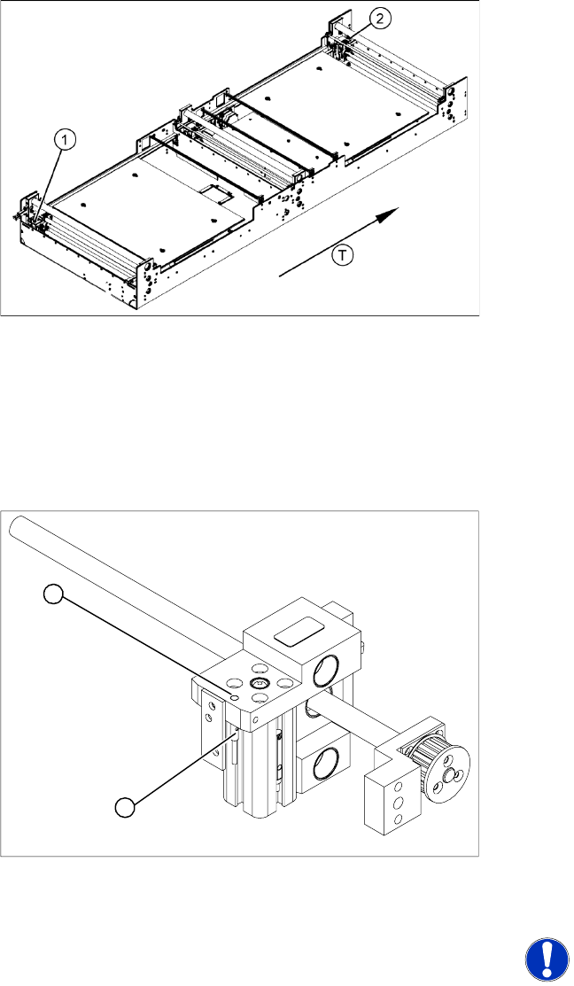
4.4.15 Replacing the Proximity Switch for the Adjustment System [00363268]
Parts
Proximity switch for adjustment unit 1 [00363268]
Proximity switch for adjustment unit 2 [00363292]
Overview
X Move the PCB conveyor to the position which gives you best access to the adjustment system.
X Move the Y gantries into the area outside the PCB conveyor.
X Switch off the machine and secure it to prevent unauthorized reactivation.
X Switch off the compressed air supply.
Removal/Installation
The proximity switch serves as a signal for
controlling the pneumatic valve of the adjustment
unit. Once the switching point has been reached,
the conveyor side is connected via the short-
stroke cylinder.
Legend
1. Adjustment unit 1
2. Adjustment unit 2
T = transport direction
X Loosen the grub screw on the clamping device
(1) and unthread the connection cable as far
as the conversion board of the assembly tray.
X Fit the new proximity switch and reconnect the
system to the electrical supply.
X Fix the proximity switch with the grub screw.
X The grub screw must be tightened with a
tightening torque of 20 Ncm (+ 3Ncm). The
proximity switch must to lie flat with the
housing (2) of the adjustment unit.
X The switching point is set at the actuator on the
conveyor side:
X Move the adjustment unit until it is under the
conveyor side.
X Place a 4/10 mm distance gauge on the
adjustment unit, press the actuator onto the
distance gauge and tighten the screw.
NOTE:
This setting must be performed at all
conveyor sides.
X Use the SITEST program to calibrate the
conveyor sides.
2
1