00195166-0402_SM_D4_EN.pdf - 第146页
Service Work Modular Conveyor Overview of the Electrical Compone nts 146 Serv ice Manual SIPLACE D4 4.4.18.5 Extension Controller Board TSP 301E for Dual Conveyors [00370398] Overview Legend 1. Conveyor contro l TSP 301E…
Service Work
Overview of the Electrical Components Modular Conveyor
Service Manual SIPLACE D4
145
4.4.18.3 Lifting Table Conversion Board [00362766]
Overview
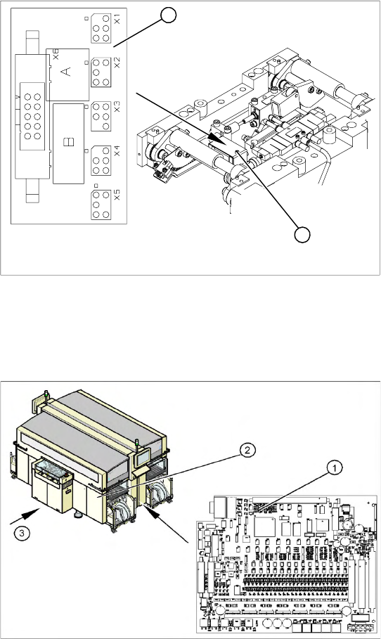
4.4.18.4 Conveyor Control TSP 301 [00370397]
Overview
Legend
1. Lifting table conversion board
2. Cover
The lifting table conversion board (1) is situated on
the lifting table unit, under the cover (2).
For terminal assignment details, please refer to
the current version of the circuit diagram folder.
1
2
Legend
1. Conveyor Control TSP 301
2. Access to conveyor control
3. Transport direction
The conveyor control TSP 301 (1) is located in the
sector distributor 1 (2). The conveyor control is
secured with a screw-off cover.
For terminal assignment details, please refer to
the current version of the circuit diagram folder.
Service Work
Modular Conveyor Overview of the Electrical Components
146 Service Manual SIPLACE D4
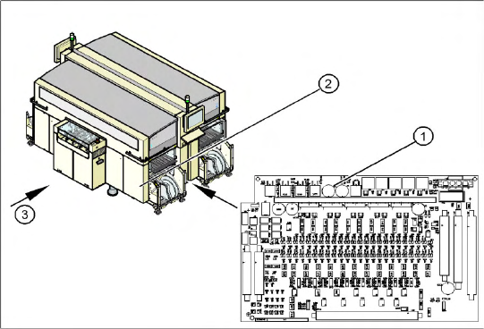
4.4.18.5 Extension Controller Board TSP 301E for Dual Conveyors [00370398]
Overview
Legend
1. Conveyor control TSP 301E
2. Access to conveyor control
3. Transport direction
The extension card for the dual conveyor TSP
301E (1) is located in the sector distributor 1 (2).
The conveyor control is secured with a screw-off
cover.
For terminal assignment details, please refer to
the current version of the circuit diagram folder.
Service Work
Replacing the C&P12 Head (D4) C&P12 Placement Head
Service Manual SIPLACE D4
147
4.5 C&P12 Placement Head
4.5.1 Replacing the C&P12 Head (D4)
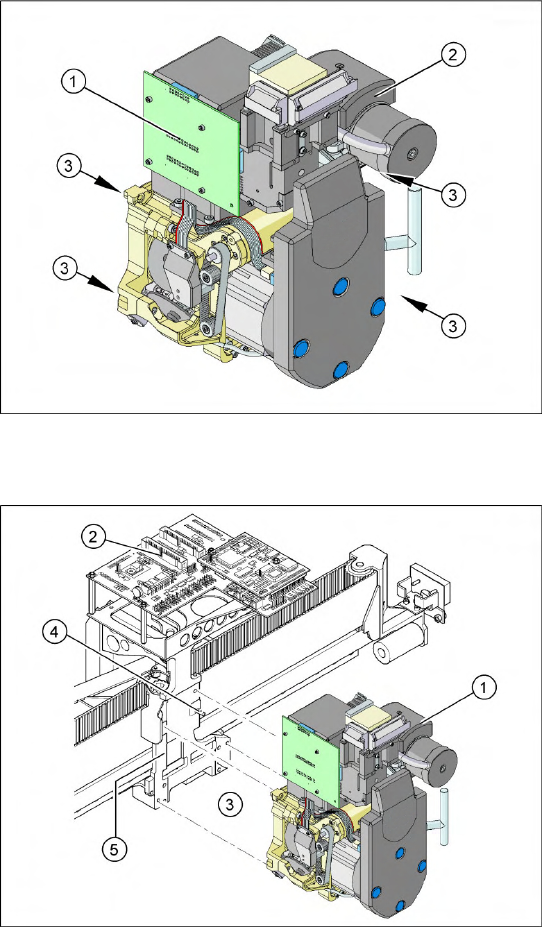
Overview
Removal
Legend
1. Illumination controller
2. Vacuum generator
3. 4 x fastening screws
Item number
C&P head DLM3 with 12 segments
[03041228-xx] (C&P12 head)
X Remove the compressed air hoses from the
pneumatic coupling of the pneumatic
distributor (1).
X Loosen the press-fit connection to the head
board (2) from the C&P head.
X Loosen the 4 screws (3) fastening the C&P
head.
X Carefully pull the C&P head off the parallel
pins (4) on the head mount (5) and remove the
head from the machine.