00195166-0402_SM_D4_EN.pdf - 第149页
Service W ork Removal/Installation of Head Front Part C&P12 P lacement Head Service Manual SIPLACE D4 149 4.5.2 Removal/Inst allati on of Head Front Part Removal Legend 1. Front part 2. Back part 3. Intermediate dist…
Service Work
C&P12 Placement Head Replacing the C&P12 Head (D4)
148 Service Manual SIPLACE D4
Installation
See also:
J
6.3.1 Calibrating the C&P Head and Cameras [
J
221]
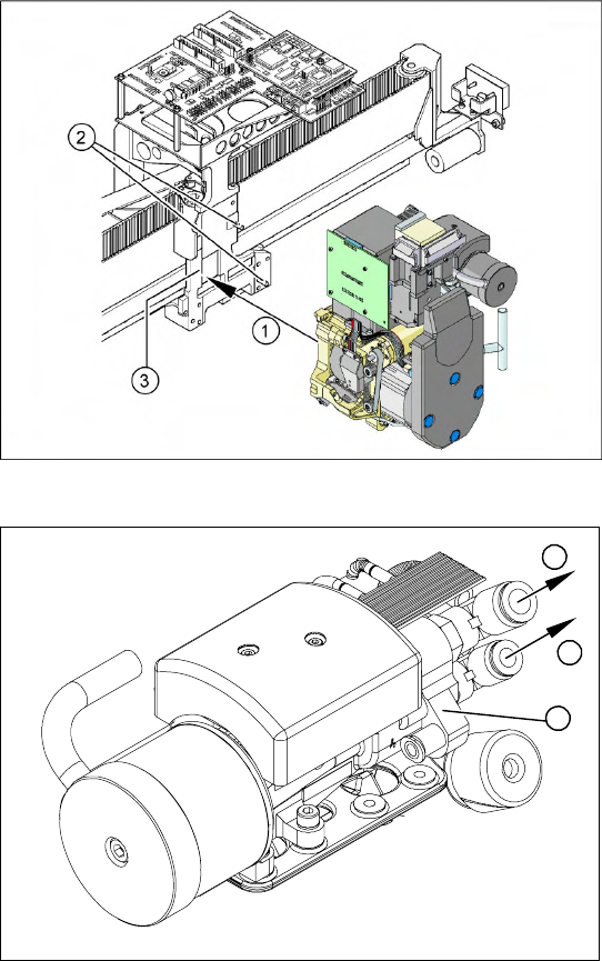
X Carefully move the C&P head towards the
head plate (3).
X Make sure that the parallel pins (2) on the
head mount slide into the holes drilled into the
back part of the C&P head.
X Carefully push the C&P head towards the
head plate until it lies flat against it.
X Fix the C&P head with the 4 screws provided
(1).
X Connect the compressed air hoses (1) to the
pneumatic coupling on the pneumatic
distributor (2).
X Reconnect to the electricity system.
X Use the SITEST program to calibrate the C&P
head.
1
1
2
Service Work
Removal/Installation of Head Front Part C&P12 Placement Head
Service Manual SIPLACE D4
149
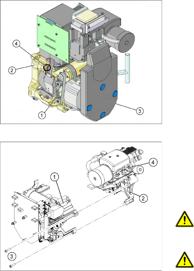
4.5.2 Removal/Installation of Head Front Part
Removal
Legend
1. Front part
2. Back part
3. Intermediate distributor (under the cover)
4. 4 x fastening screws
X Switch off the machine and secure it to prevent
unauthorized reactivation.
X Remove the connecting cable plugs from the
sockets on the gantry head distributor or head
interface and the head adapter.
X Remove the compressed air hose for the air
blast (4).
X Loosen the four fastening screws (3).
ATTENTION: Hold on to the
placement head!
When you undo the last screw, hold the
C&P head so that it does not
accidentally drop off the back part.
ATTENTION: Make sure the star
position is correct!
When you remove the front part of the
C&P head, make sure that the star is
rotated roughly 30° or 15° out of the
vertical sleeve position. otherwise the
valve plunger will remain attached to
the valve adjustment drive.
X Pull the front part of the C&P head (1) off the
parallel pins on the back part (2) and place it
on a clean, soft surface.
Service Work
C&P12 Placement Head Removal/Installation of Head Front Part
150 Service Manual SIPLACE D4
Installation
See also:
J
6.3.1 Calibrating the C&P Head and Cameras [
J
221]
X Grease the O-rings of the vacuum distributor
with Unisilkon.
X Push the small O-ring onto the tube.
X Place the large O-ring on the vacuum
distributor piece (4).
X Check that the O-rings are seated correctly.
X Insert the distributor block into the back part
(3).
ATTENTION:
Star position 15°!
X Make sure that all contact surfaces and pins
are clean.
X Place the front part (2) on the back part (3) so
that the parallel pins are aligned with the holes
in the front part.
X Carefully push the front part against the back
part until it lies flat against the back part.
X Tighten the four fastening screws.
X Reconnect to the electrical and compressed
air systems.
ATTENTION: Check how the cables
are run!
Make sure that the folded part of the
ribbon cable for the "Z axis up" light
barrier is pushed back under the
illumination board.
X Use the SITEST program to calibrate the C&P
head.
1
4
3
2