00195166-0402_SM_D4_EN.pdf - 第158页
Service Work C&P12 Placement Head Replacing the Toothed Belt for the D LM Turning Station (from version 07) 158 Serv ice Manual SIPLACE D4 4.5.7 Replacing the T oothed Belt for the DLM T urning St ation (from version…
Service Work
Replacing the DP Rocker C&P12 Placement Head
Service Manual SIPLACE D4
157
Installation
X Fit the drive arm (3) with drive wheel back on
the swivel-in ball bearing.
X Swivel the rocker arm on the motor back and
refit the M2x3.5 screws.
X See also section (4.5.7 Replacing the Toothed
Belt for the DLM Turning Station (from version
07) [00320041-xx]
J
158 ) for the following
tasks.
X Place the belt back on the drive wheel and pull
it over the motor toothed wheel.
X Fit the belt tensioning device for the DP
station.
X Tighten the two screws.
NOTE:
X When replacing the DP rocker, you
also need to replace the drive
toothed belt.
X The version 7 DP station with new
rocker should be available from early
2009 onwards.
Service Work
C&P12 Placement Head Replacing the Toothed Belt for the DLM Turning Station (from version 07)
158 Service Manual SIPLACE D4
4.5.7 Replacing the Toothed Belt for the DLM Turning Station (from version 07)
[00320041-xx]
Removal/Installation
NOTE:
The version 7 turning station should be available from early 2009 onwards.
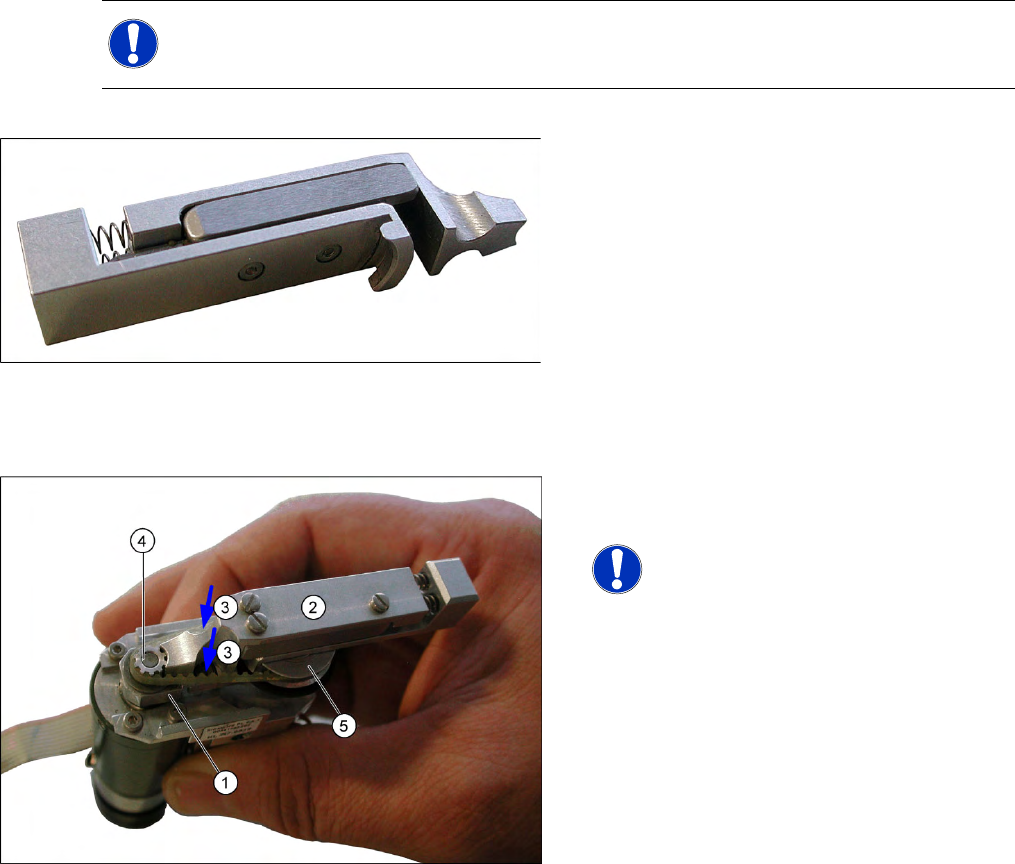
4-42: Belt tensioning device for turning station DLM
Tools and equipment
Standard tool
Belt tensioning device for DLM turning station
Item No. [03063649-01]
Lubricant Isoflex Topas NCA52
Spare part: Synchroflex toothed belt 2.5 T2/90
[00320041-01]
X Remove the turning station as described in the
previous chapter.
NOTE:
X To loosen or tighten the fastening
screw on the rocker, hold the DP
station between your thumb and
index finger so that the swivel-in
rocker (1) can be moved to the left
and right.
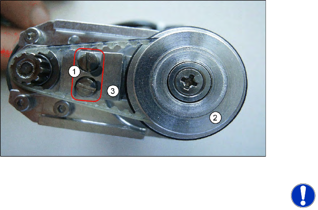
X Remove the defective toothed belt.
X Loosen the two fastening screws (3) with a
size 0 screwdriver. Do not fully remove these
screws - leave them in the unit.
X Grease the new toothed belt slightly with
Isoflex Topas NCA52.
X Fit the new toothed belt onto the toothed
wheels.
X Fit the adjustment aid (2) between the motor
drive toothed wheel (4) and the sleeve drive
wheel (5). The tension of the steel spring in the
tool sets the belt to the correct tension.
X Now tighten the two screws fastening (3) the
rocker with a size 0 screwdriver.
X Check the axis dynamics according to the
setting instructions for the machine and
relevant placement head..
X Refit the turning station as described in the
previous chapter.
Service Work
Replacing the Valve Positioning Drive for the Placement Circuit [00368075] C&P12 Placement Head
Service Manual SIPLACE D4
159
4.5.8 Replacing the Valve Positioning Drive for the Placement Circuit [00368075]
Tools and equipment
Standard tool
Distance gauge 0.2 mm [00325445-01] – used up to version 2:
Adjustment valve plunger – available from version 3, valid for DLM2 and DLM3 (use the 0.2 setting
gauge for DLM1)
Removal
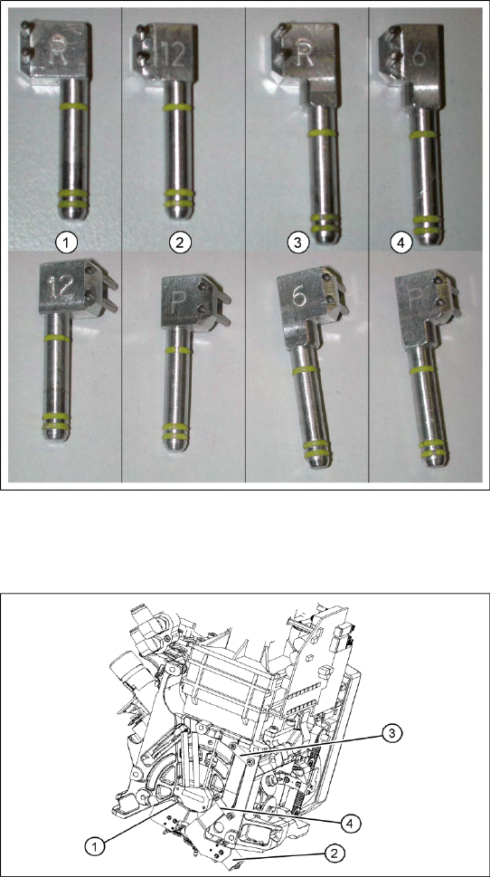
4-43: C&P6/12 adjustment valve plunger
Legend
1. Adjustment valve plunger for reject circuit
C&P12 [03064290-01]
2. Adjustment valve plunger for placement circuit
C&P12 [03068816-01]
3. Adjustment valve plunger for reject circuit
C&P6 [03068854-01]
4. Adjustment valve plunger for placement circuit
C&P6 [03065628-01]
The labeling on the plungers has the following
meaning:
6 = C&P6
12 = C&P12
P = placement circuit
R = reject circuit
Legend
1. Valve positioning drive for the placement
circuit [00368075]
2. Valve positioning drive for the reject circuit
[00367768]
3. Flat ribbon cable clamp
4. Flat ribbon cable clamp
X Dismantle the C&P head.
X Loosen the two M2x6 Phillips screws on the
flat ribbon cable clamp (3) and (4).