00195166-0402_SM_D4_EN.pdf - 第162页
Service Work C&P12 Placement Head Replacing the Valve Positi oning Drive for the Placement Circuit [00368075] 162 Serv ice Manual SIPLACE D4 X Use the feeler ga uge to set the distance between the va lve plu nger and…
Service Work
Replacing the Valve Positioning Drive for the Placement Circuit [00368075] C&P12 Placement Head
Service Manual SIPLACE D4
161
4.5.8.1 New Valve Positioning Drives (From Version 03)
New valve positioning drives are now available which guarantee a reliable assembly position even if the
placement head is incorrectly placed down on its back.
The valve positioning drive can ONLY be fitted when the placement head has been dismantled, as the
locking threaded pin (Allen key, M1, 4x4) is only accessible from the back of the head.
4.5.8.2 Mechanical Adjustment (Up To Version 02)
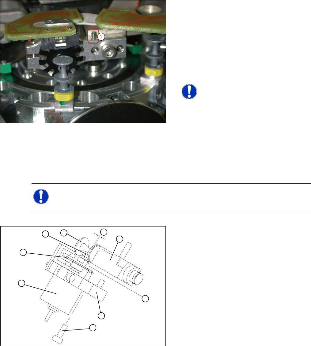
4-44: New valve positioning drive holder for star placement position with
position locking
The holder for the valve positioning drives of the
placement and reject positions has an additional
threaded pin. After the motor mount has been
fastened, this threaded pin is tightened until it just
touches the centering pin. The valve positioning
drive is now fixed so that its position can not
change towards the front.
Additional improvements have also been made to
individual parts of the valve positioning drive.
NOTE:
This holder also fits the valve
positioning drive on the placement and
reject position of the DLM1 placement
head. A second 1.4 mm thread (1) is
provided on the opposite side for this
purpose.
NOTE:
Instead of using the adjustment valve plungers, the DLM1 and DLM2 heads can also be set with
the distance gauge.
Legend
1. Stepping motor
2. Cam disk
3. Deep-groove ball bearings
4. Valve plunger
5. Valve casing
6. M3x10 hexagon socket-head screw
7. Valve positioning drive (flange)
B
A
1
7
6
5
4
3
2
Service Work
C&P12 Placement Head Replacing the Valve Positioning Drive for the Placement Circuit [00368075]
162 Service Manual SIPLACE D4
X Use the feeler gauge to set the distance
between the valve plunger and valve casing to
0.2 mm (A).
X Turn the cam disk (2) until the deep-groove
ball bearings (3) point towards the valve
casing.
X Move the valve positioning drive (7) so that the
deep-groove ball bearings (3) come into
contact with the valve plunger (4) at position
(B).
X Use the hexagon socket-head screw to fix the
adjustment unit in this position (6).
X Fit the C&P head.
X Use the SITEST program to test that the valve
positioning drive is functioning correctly.
X Use the SITEST program to calibrate the C&P
head.
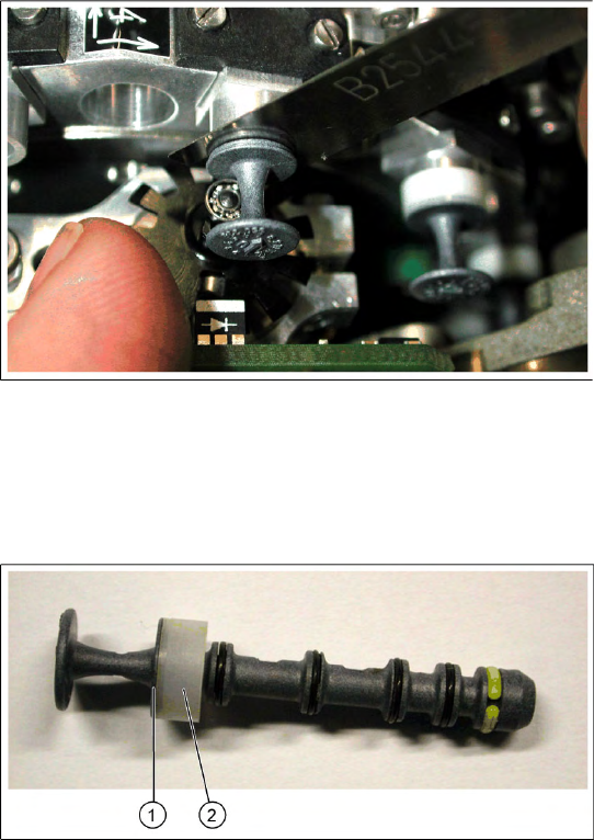
4-45: Valve plunger version 03 (C&P12: [00351498-03], C&P6: [00351500-
03])
X If the new valve plungers are used (s. diag. on
left) proceed as follows:
Take out one valve plunger and remove the
sleeve (2).
Insert the plunger without bushing and carry
out the following steps on this segment:
X Insert the distance gauge (0.2 mm) between
valve plunger and valve casing.
X Rotate the valve positioning drive 90 degrees
from its initial position. The eccentric of the
valve adjustment drive will just touch the inner
side (1) of the valve plunger.
X Fix the motor of the valve drive in this position.
X Remember to replace the tube on the valve
plunger.
Service Work
Replacing the Valve Positioning Drive for the Placement Circuit [00368075] C&P12 Placement Head
Service Manual SIPLACE D4
163
4.5.8.3 Mechanical Adjustment (All Versions)
Setting the valve positioning drive for the placement position
NOTE:
The DLM1 (placement position) and all valve positioning drives of the DLM2 and DLM3 heads
can be set with the adjustment valve plungers.
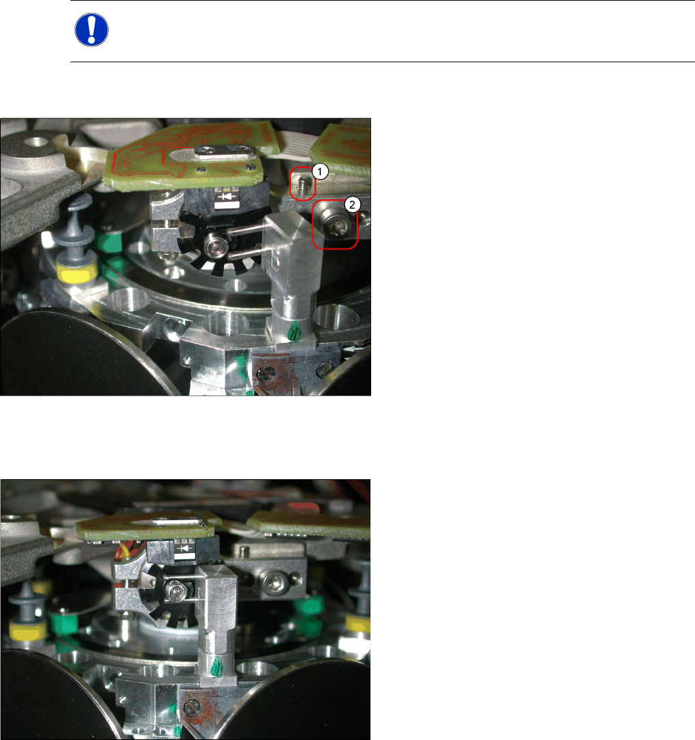
X Fit the dismantled placement head onto the
head mount and place both down on the front
or place the placement head down on a soft,
ESD conductible surface on its front.
X The lockscrew (1) and the fastening screw (2)
of the valve positioning drive need to be
loosened or are only screwed in slightly during
assembly of the drive.
X Instead of using a valve plunger, the
adjustment plunger is now inserted for the
placement position (P), as can be seen in the
diagram.
X Turn the adjustment valve plunger so that the
tips of the two centering pins are near to the
cam disk behind the ball bearing. Use a
pointed object to carefully turn the cam disk so
that it is in the "starting position" (ball bearing
horizontally aligned next to the drive shaft).
X Carefully turn the star to the valve positioning
drive so that the two centering pins behind the
ball bearing grasp the fixtures on the cam disk.
The adjustment valve plunger swivels into the
correct position (centering pins parallel to cam
disk).