00195166-0402_SM_D4_EN.pdf - 第164页
Service Work C&P12 Placement Head Replacing the Valve Positi oning Drive for the Placement Circuit [00368075] 164 Serv ice Manual SIPLACE D4 X Press the valve positioning dr ive in the direction of the placement star…
Service Work
Replacing the Valve Positioning Drive for the Placement Circuit [00368075] C&P12 Placement Head
Service Manual SIPLACE D4
163
4.5.8.3 Mechanical Adjustment (All Versions)
Setting the valve positioning drive for the placement position
NOTE:
The DLM1 (placement position) and all valve positioning drives of the DLM2 and DLM3 heads
can be set with the adjustment valve plungers.
X Fit the dismantled placement head onto the
head mount and place both down on the front
or place the placement head down on a soft,
ESD conductible surface on its front.
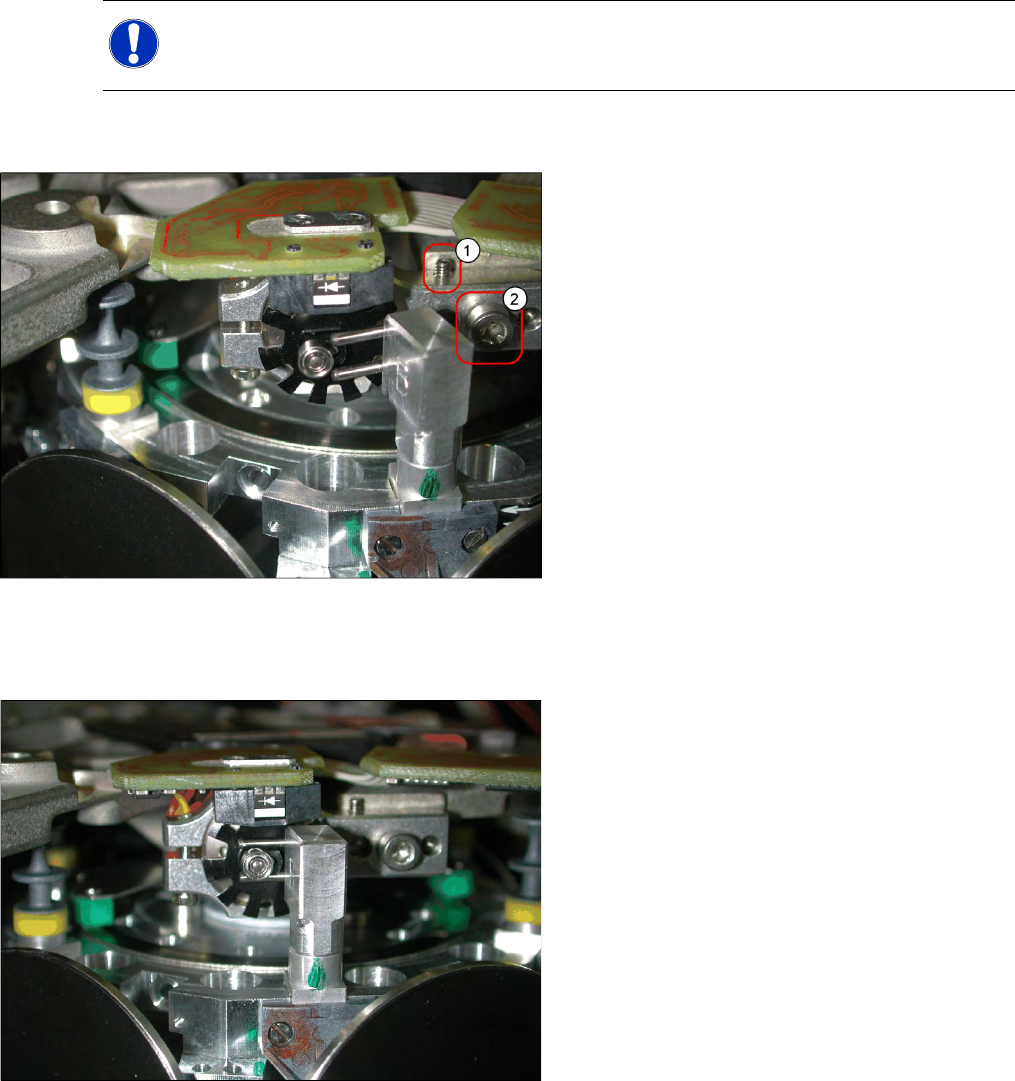
X The lockscrew (1) and the fastening screw (2)
of the valve positioning drive need to be
loosened or are only screwed in slightly during
assembly of the drive.
X Instead of using a valve plunger, the
adjustment plunger is now inserted for the
placement position (P), as can be seen in the
diagram.
X Turn the adjustment valve plunger so that the
tips of the two centering pins are near to the
cam disk behind the ball bearing. Use a
pointed object to carefully turn the cam disk so
that it is in the "starting position" (ball bearing
horizontally aligned next to the drive shaft).
X Carefully turn the star to the valve positioning
drive so that the two centering pins behind the
ball bearing grasp the fixtures on the cam disk.
The adjustment valve plunger swivels into the
correct position (centering pins parallel to cam
disk).
Service Work
C&P12 Placement Head Replacing the Valve Positioning Drive for the Placement Circuit [00368075]
164 Service Manual SIPLACE D4
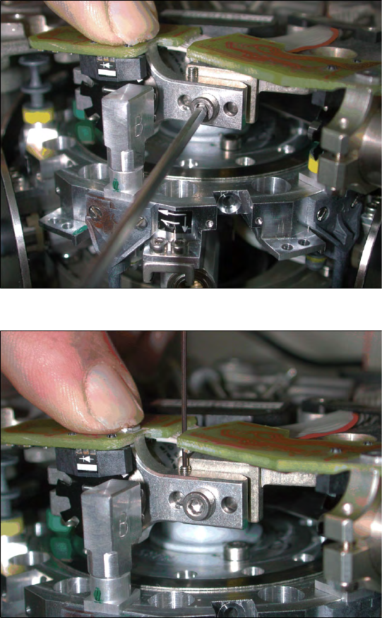
X Press the valve positioning drive in the
direction of the placement star and fasten the
drive holder with the 2.5 mm Allen key.
X Now tighten the locking threaded pin with an
Allen key of size 0.89 mm. Press the valve
positioning drive against it. Do not tighten
excessively as this could push the valve
positioning drive "backwards".
X Remove the adjustment plunger by turning the
placement star back and then rotating the
adjustment plunger out of the valve housing.
Service Work
Replacing the Valve Positioning Drive for the Reject Circuit [00367768] C&P12 Placement Head
Service Manual SIPLACE D4
165
4.5.9 Replacing the Valve Positioning Drive for the Reject Circuit [00367768]
Tools and equipment
Standard tool
Used up to version 2: distance gauge 0.2 mm [00325445-01]
Available from version 3, valid for all versions: adjustment valve plunger
Removal
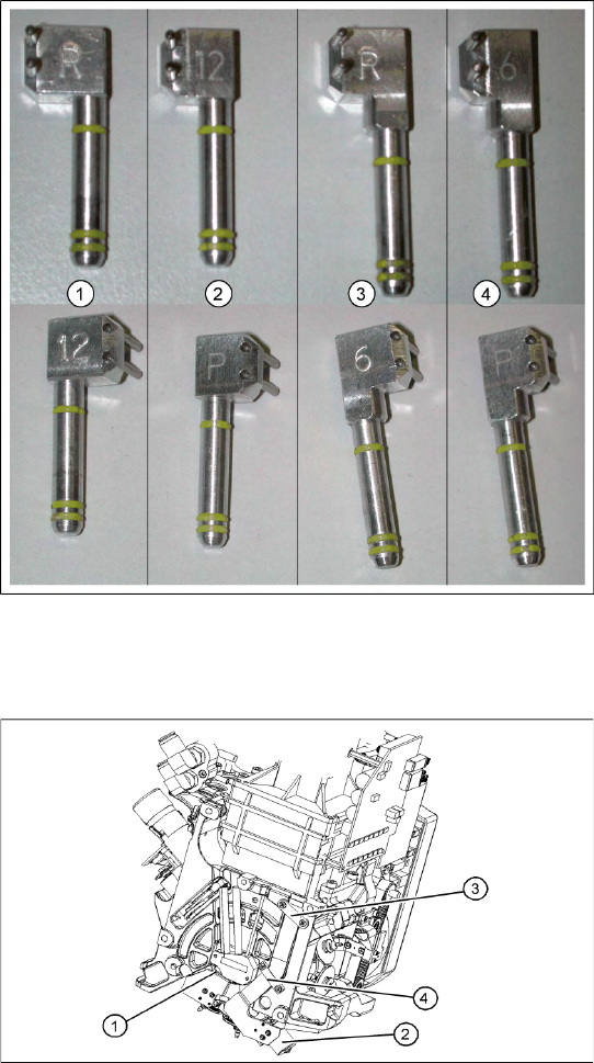
4-46: C&P6/12 adjustment valve plunger
Legend
1. Adjustment valve plunger for reject circuit
C&P12 [03064290-01]
2. Adjustment valve plunger for placement circuit
C&P12 [03068816-01]
3. Adjustment valve plunger for reject circuit
C&P6 [03068854-01]
4. Adjustment valve plunger for placement circuit
C&P6 [03065628-01]
The labeling on the plungers has the following
meaning:
6 = C&P6
12 = C&P12
P = placement circuit
R = reject circuit
Legend
1. Valve positioning drive for the placement
circuit [00368075]
2. Valve positioning drive for the reject circuit
[00367768]
3. Flat ribbon cable clamp
4. Flat ribbon cable clamp
X Dismantle the C&P head.
X Loosen the two M2x6 Phillips screws on the
flat ribbon cable clamp (3) and (4).