00195166-0402_SM_D4_EN.pdf - 第169页
Service W ork Replacing the Valve Positioning Drive for the Reject Circuit [00 367768] C&P12 Placement Head Service Manual SIPLACE D4 169 4.5.9.3 Mechanical Adjustment (From V ersion 03) Setting the valve positioning…
Service Work
C&P12 Placement Head Replacing the Valve Positioning Drive for the Reject Circuit [00367768]
168 Service Manual SIPLACE D4
X Use the feeler gauge to set the distance
between the valve plunger and valve casing to
0.2 mm (A).
X Turn the cam disk (2) until the deep-groove
ball bearings (3) point towards the valve
casing.
X Move the valve positioning drive (7) so that the
deep-groove ball bearings (3) come into
contact with the valve plunger (4) at position
(B).
X Use the hexagon socket-head screw to fix the
adjustment unit in this position (6).
X Fit the C&P head.
X Use the SITEST program to test that the valve
positioning drive is functioning correctly.
X Use the SITEST program to calibrate the C&P
head.
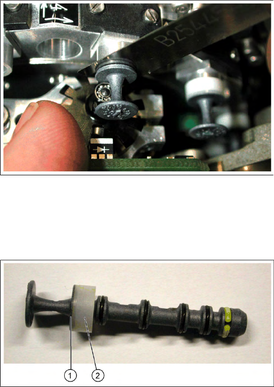
4-48: Valve plunger version 03 (C&P12: [00351498-03], C&P6: [00351500-
03])
X If the new valve plungers are used (s. diag. on
left) proceed as follows:
Take out one valve plunger and remove the
sleeve (2).
Insert the plunger without bushing and carry
out the following steps on this segment:
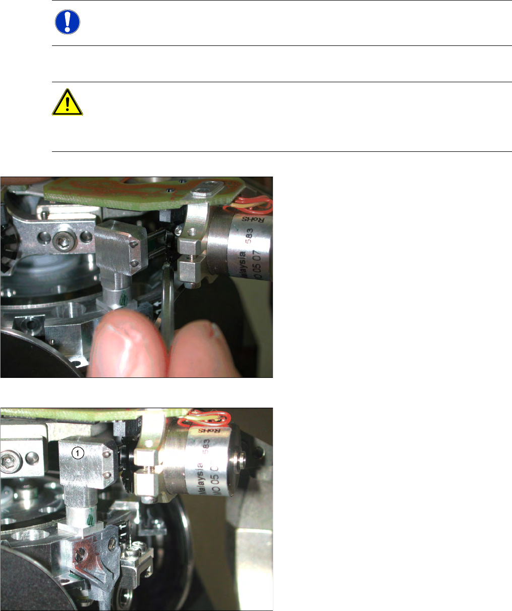
X Insert the distance gauge (0.2 mm) between
valve plunger and valve casing.
X Rotate the valve positioning drive 90 degrees
from its initial position. The eccentric of the
valve adjustment drive will just touch the inner
side (1) of the valve plunger.
X Fix the motor of the valve drive in this position.
X Remember to replace the tube on the valve
plunger.
Service Work
Replacing the Valve Positioning Drive for the Reject Circuit [00367768] C&P12 Placement Head
Service Manual SIPLACE D4
169
4.5.9.3 Mechanical Adjustment (From Version 03)
Setting the valve positioning drive for the reject position
NOTE:
The valve positioning drives of the DLM1 and DLM3 head reject position can be set with the
adjustment valve plungers.
ATTENTION:
Even if your placement machine does not use the valve positioning drive for rejecting
components (rejection vertically down), the position of this drive must still be correct. If this is
not the case, an incorrectly set valve positioning drive could have a negative influence on the
plunger positions during the reference run and during star rotation.
X Fit the dismantled placement head onto the
head mount and place this down on the front
or place the placement head down on a soft,
ESD conductible surface on its front.
X The lockscrew (at the bottom side of the
placement head) and the fastening screw of
the valve positioning drive need to be
loosened or are only screwed in slightly during
assembly of the drive.
X Fit the adjustment valve plunger (1) in place of
the valve plunger, for the reject position (R) -
as shown in the diagram.
X Turn the adjustment valve plunger so that the
tips of the two centering pins are near to the
cam disk behind the ball bearing.
Service Work
C&P12 Placement Head Replacing the Valve Positioning Drive for the Reject Circuit [00367768]
170 Service Manual SIPLACE D4
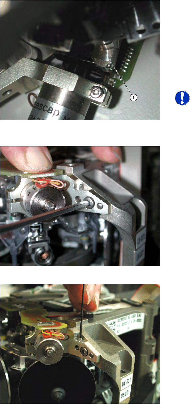
X Use a pointed object to carefully turn the cam
disk so that it is in the "starting position" (ball
bearing horizontally aligned next to the drive
shaft).
X Carefully turn the placement star in the
direction of the valve positioning drive so that
the two centering pins behind the ball bearing
grasp the fixtures on the cam disk. The
adjustment valve plunger (1) swivels into the
correct position (centering pins parallel to cam
disk).
NOTE:
As the cam disk of the reject valve
positioning drive is behind the
connection board, this setting is slightly
more complex than that for the
placement circuit.
X Press the valve positioning drive in the
direction of the placement star and fasten the
drive holder with a 2.5 mm Allen key.
X Now tighten the locking threaded pin with an
Allen key of size 0.89 mm. Press the valve
positioning drive against it. Do not tighten
excessively as this could push the valve
positioning drive "backwards".
X Remove the adjustment plunger by turning the
placement star back and then rotating the
adjustment plunger out of the valve housing.
X Then replace the adjustment plunger with a
plunger and protection ring.