00195166-0402_SM_D4_EN.pdf - 第171页
Service W ork Replacing the Light Barrier "Z Axis U p" [03053294-xx] C&P12 Placement Head Service Manual SIPLACE D4 171 4.5.10 Replacing the Light Ba rrier "Z Axis Up" [03053294-xx] Removal Instal…
Service Work
C&P12 Placement Head Replacing the Valve Positioning Drive for the Reject Circuit [00367768]
170 Service Manual SIPLACE D4
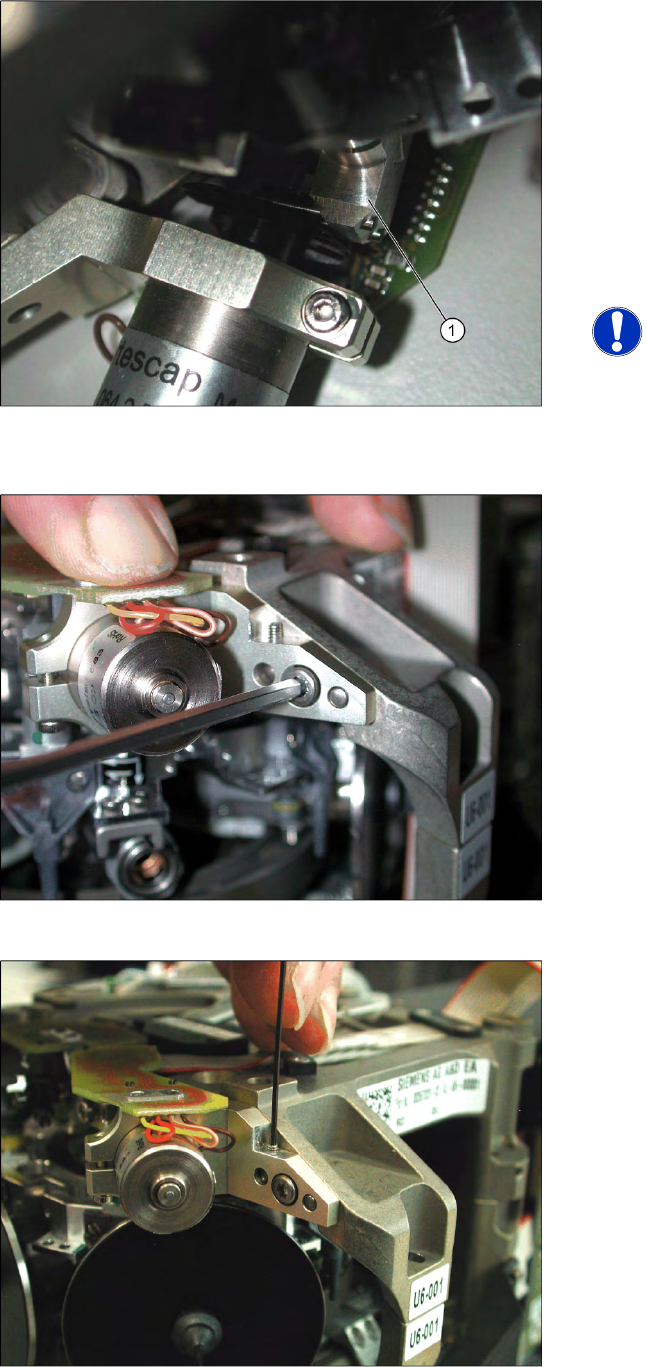
X Use a pointed object to carefully turn the cam
disk so that it is in the "starting position" (ball
bearing horizontally aligned next to the drive
shaft).
X Carefully turn the placement star in the
direction of the valve positioning drive so that
the two centering pins behind the ball bearing
grasp the fixtures on the cam disk. The
adjustment valve plunger (1) swivels into the
correct position (centering pins parallel to cam
disk).
NOTE:
As the cam disk of the reject valve
positioning drive is behind the
connection board, this setting is slightly
more complex than that for the
placement circuit.
X Press the valve positioning drive in the
direction of the placement star and fasten the
drive holder with a 2.5 mm Allen key.
X Now tighten the locking threaded pin with an
Allen key of size 0.89 mm. Press the valve
positioning drive against it. Do not tighten
excessively as this could push the valve
positioning drive "backwards".
X Remove the adjustment plunger by turning the
placement star back and then rotating the
adjustment plunger out of the valve housing.
X Then replace the adjustment plunger with a
plunger and protection ring.
Service Work
Replacing the Light Barrier "Z Axis Up" [03053294-xx] C&P12 Placement Head
Service Manual SIPLACE D4
171
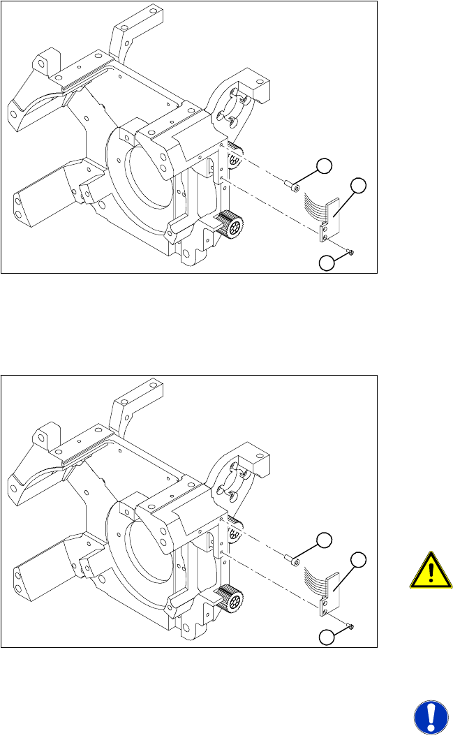
4.5.10 Replacing the Light Barrier "Z Axis Up" [03053294-xx]
Removal
Installation
Legend
1. 2 x M2.0x4 hexagon socket-head screws
2. 2 Phillips screws (1.6x3)
3. Light barrier board "Z axis up"
X Switch off the machine and secure it to prevent
unauthorized reactivation.
X Remove the plug from the slot on the
intermediate distributor.
X Undo the two M2.0x4 hexagon socket-head
screws (1) and remove the ribbon cable
clamp.
X Loosen the two M1.6x3 Phillips screws (2).
X Remove the light barrier "Z axis up" (3) with its
cable.
1
3
2
X Use the two M1.6x3 Phillips screws (2) to fix
the "Z axis up" light barrier board (3). Move the
board as far upwards as the screws will
tolerate.
X Connect the ribbon cable plug to the slot on
the intermediate distributor.
X Use the flat ribbon cable clamp and the two
hexagon socket-head screws (1) to fix the flat
ribbon cables.
ATTENTION: Check how the cables
are run!
Make sure that the flat ribbon cable is
not pinched in the guide channel.
Make sure that you push the folded part
of the flat ribbon cable for the "Z axis
up" light barrier back under the
illumination board.
NOTE: Shortened cable
A new version is available with a
shortened flat ribbon.
1
3
2
Service Work
C&P12 Placement Head Replacing the Z Axis Drive [00341011]
172 Service Manual SIPLACE D4
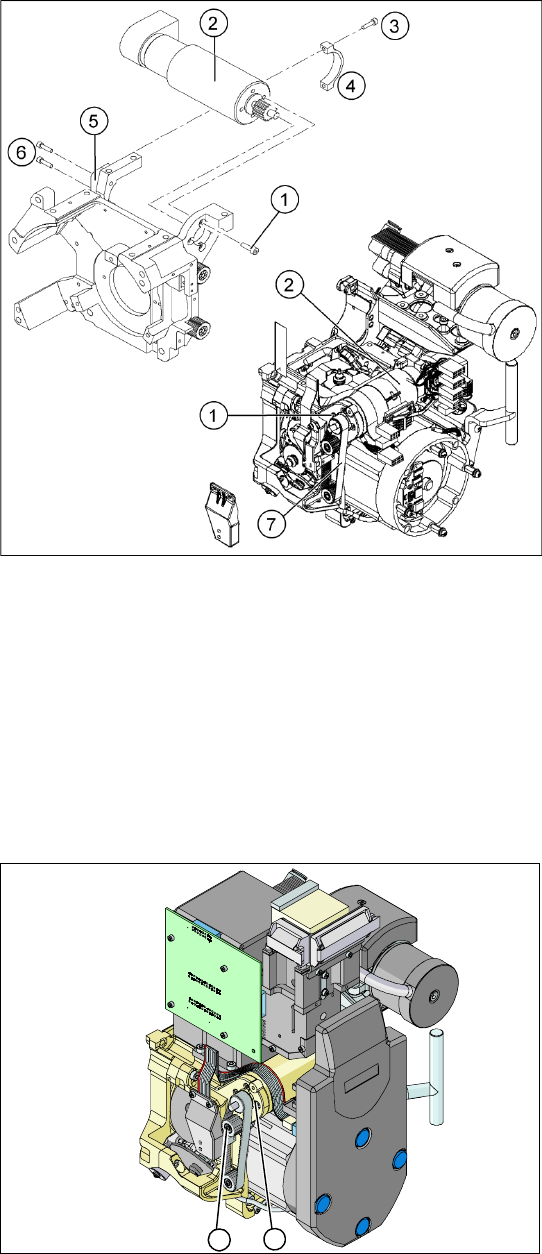
4.5.11 Replacing the Z Axis Drive [00341011]
Removal
Installation
Legend
1. 4 x M3x5 hexagon socket-head screws with
locking varnish
2. Z axis drive
3. 2 x M2.5x12 hexagon socket-head screws
4. Motor clamp upper part /DLM3
5. Motor clamp/DLM3 (do not confuse this with
the assembly clamp for the Z motor tacho
interference suppression board)
6. 2 x M3x14 hexagon socket-head screws
7. Toothed belt
X Switch off the machine and secure it to prevent
unauthorized reactivation.
X Remove the plugs (motor tacho and
incremental encoder) from the sockets on the
intermediate distributor.
X Loosen the four M3x5 hexagon socket-head
screws which have been fixed with locking
varnish (1).
X First loosen the upper M2.5x12 hexagon
socket-head screw (3) of the motor clamp
fitting 2 (4), then the lower one.
X Loosen the two M3x14 hexagon socket-head
screws (6) on the motor clamp fitting (5).
X Carefully remove the Z axis drive (2) together
with the cables.
X Insert the Z axis drive (2).
X Make sure that the teeth of the toothed belt (7)
engage in the teeth of the motor pinion (1).
X Use the four M3x5 hexagon socket-head
screws to fit the Z axis drive.
X Tension the Z axis toothed belt by moving the
Z axis drive unit upwards and fix the motor with
at least one screw.
X Check the toothed belt tension with the belt
tension measuring device.
2
1