00195166-0402_SM_D4_EN.pdf - 第176页
Service Work C&P12 Placement Head Replacing the "Z Axis Dow n" Sensor [00321524 -xx] 176 Serv ice Manual SIPLACE D4 4.5.13 Replacing the "Z Axis Down" Sensor [00321524-xx] Removal Installation Leg…
Service Work
Replacing the Z Axis Toothed Belt [00334936] C&P12 Placement Head
Service Manual SIPLACE D4
175
See also:
J
6.3.6 Setting the Z axis Belt Tension [
J
227]
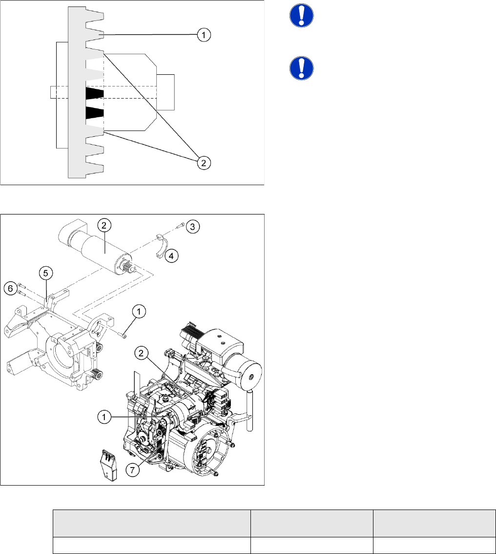
NOTE:
Make sure that both ends (2) of the
tension jack lie on the teeth of the
toothed belt (1) .
NOTE: New tension jack
A new tension jack (fitted from 10/
2007) has a profile which engages with
the toothed belt and therefore ensures
a more reliable clamping.
X Loosely screw in the four M3x5 hexagon
socket-head screws (1) on the Z axis drive unit
(2).
X Tension the Z axis toothed belt (7) by pushing
the Z axis drive unit upwards.
X Check the toothed belt tension with the belt
tension measuring device.
X Tighten the two M3x14 hexagon socket-head
screws (6) to fix the motor clamp (5).
X Fix the motor clamp 2 (4) with the two
M2.5x12 hexagon socket-head screws (3).
X Now tighten the hexagon socket-head screws
on the Z axis drive unit and the motor clamp.
X Check the Z axis top stop with the adjustment
gauge.
Frequency in Hz Before continuous
operation
After continuous operation
Toothed belt T2 / DLM3 on the Z axis 280 +/- 10 280 +/- 10
Service Work
C&P12 Placement Head Replacing the "Z Axis Down" Sensor [00321524-xx]
176 Service Manual SIPLACE D4
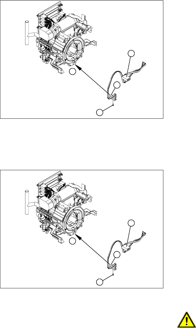
4.5.13 Replacing the "Z Axis Down" Sensor [00321524-xx]
Removal
Installation
Legend
1. "Z axis down" sensor
2. Fixtures for sensor
3. Plug for intermediate distributor
X Dismantle the front part of the C&P head.
X Dismantle the star.
X Remove the plug from the slot on the
intermediate distributor.
X Push the Z axis down.
X Loosen the screws holding the sensor (2).
X Remove the cable clamps on the driver arm
and star motor.
X Carefully pull the sensor and cable out of the
front part of the C&P head and remove the
plug (3) from the socket on the intermediate
distributor.
1
1
3
2
X Thread the sensor cable from the Z axis into
the front part of the C&P head.
X Fix the sensor (1) in position with the screw
provided (2) and initially screw loosely into the
jaw of the Z axis.
X Fix the cable into place with the cable clamps.
X Check how the cable is run inside the front part
of the C&P head:
If the Z axis has been pushed right out, the
cable should lie loosely around the housing for
the star drive shaft. The cable must NOT be
pulled tight.
If the Z axis is pushed right in, the cable should
run freely inside the front part of the C&P head,
without touching the rotary encoder of the DP
axis.
ATTENTION: Check how the cables
are run!
If the radius of the curvature is too
small, the Z axis could jam or the light
barrier cable could break.
X Once the cable is run in line with the required
conditions, fix it in place with the cable clamps.
X Connect the cable plug to the slot on the
intermediate distributor.
1
1
3
2
Service Work
Replacing the Complete Z Axis [03001959] C&P12 Placement Head
Service Manual SIPLACE D4
177
Adjustment
X Set the distance between the white sleeve ring and the light barrier to 0.95 -1.15 mm.
Use a test probe or drill (diameter 1.0 mm) for this.
Check the distance with a test probe or drill (diameter 1.2 mm). – This drill should not fit!
X Fix the light barrier in place with the two screws provided.
X Fit and adjust the star.
X Fit the front part of the C&P head.
X Use the SITEST program to check that the sensor is working correctly.
See also:
J
6.3.1 Calibrating the C&P Head and Cameras [
J
221]
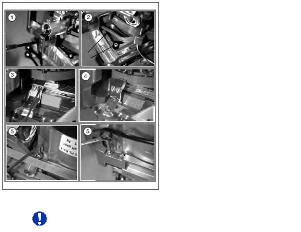
4.5.14 Replacing the Complete Z Axis [03001959]
X Move the changeover table out of the
machine.
X Switch off the machine.
X Remove the front part of the C&P head. (See
section (4.5.2 Removal/Installation of Head
Front Part
J
149 ) .)
X (1) Dismantle the light barrier under the Z axis,
by loosening the two M1.6x3 DIN 84 screws.
X (2) Carefully pull the cable out of the cable duct
until it lies loosely.
X (3) Loosen the connection between the driver
arm and driver bracket by removing the two
M2x14 DIN 912 screws.
X (4) Pull the driver arm, together with the
centering pin, out of the driver bracket and
move the driver arm into the stop position in
the raceway.
X (5) Remove the three screws holding the Z
axis in place (2x M3x14, 1x M3x4).
NOTE:
We recommend replacing the complete Z axis DLM3 after approx. 100 million placements.