00195166-0402_SM_D4_EN.pdf - 第183页
Service W ork Replacing the Star [00341181] C&P12 P lacement Head Service Manual SIPLACE D4 183 ATTENTION: The power pack operating time is limite d! The maximum operating time for the power pack of the star motor is…
Service Work
C&P12 Placement Head Replacing the Star [00341181]
182 Service Manual SIPLACE D4
Installation
4.5.17.1 Adjusting the Star to the Star's Magnetic Neutral Position
When adjusting the star, the aim is to make sure the vertically aligned segment axis of segment No. 1
corresponds with the magnetic neutral position of the star stepping motor.
X To do this, fit the star zero point gauge and insert the gauge pin into the gauge for the star and into
segment no. 1, until it reaches the stop.
X Pull the motor line plug of the star motor off the slot on the intermediate distributor and connect the
motor line to the power supply.
X Connect the power supply unit to the mains power.
X Tighten the three M3x8 hexagon socket-head screws on the star and remove the gauge pin.
X To do this, reinsert the gauge pin into the star gauge and insert into the segment, until it reaches the
stop.
X Disconnect the power pack from the power source.
X Please check:
That the gauge pin can be inserted easily.
That the star does not rotate out of its current position as a result.
If both of these conditions are fulfilled, the star has been fitted correctly.
X Repeat the adjustment procedure if the gauge pin does not slide easily into the hole.
NOTE:
X Remove any remaining sleeves
before fitting the star.
X Wear laboratory gloves when you
remove the sleeves from the star.
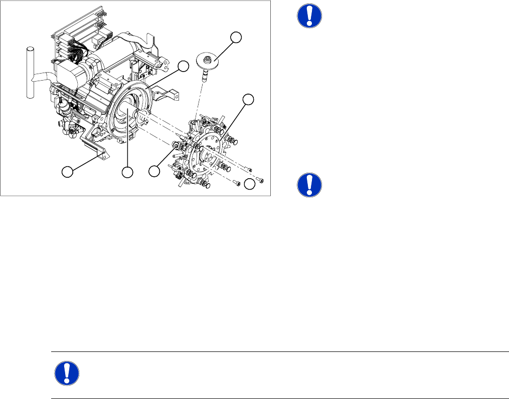
X Push all the segments (6) slightly outwards.
X Insert small Allen keys (e.g. size 2) into the
holes for the star fastening screws (5).
X Hold the star over the star drive shaft (3), so
that the Allen keys slide into the threaded
holes in the star drive.
X Insert the star.
NOTE:
Make sure that the vacuum hoses of
the segments are not pinched.
X Push all the segments inwards so that the
segment ball bearings slide into the raceway
(7).
X Check that the star is seated flat on the drive
shaft.
X Loosely tighten the three M3x8 hexagon
socket-head screws on the star so that the
screws can still move slightly in the fixing
holes.
1
7
6
5
4
3
2
NOTE: You may need to slightly grease the valve plunger.
Grease the sealing lips economically with the greasing tool or with a lint-free cloth coated with
ISOFLEX TOPAS NCA 52. (see service manual "Servicing the Valve Plunger")
Service Work
Replacing the Star [00341181] C&P12 Placement Head
Service Manual SIPLACE D4
183
ATTENTION: The power pack operating time is limited!
The maximum operating time for the power pack of the star motor is five minutes. Do NOT
exceed this time If you have to disconnect the power pack from the power source because it has
been operating for five minutes, always insert the gauge pin before switching the power pack
back on again.
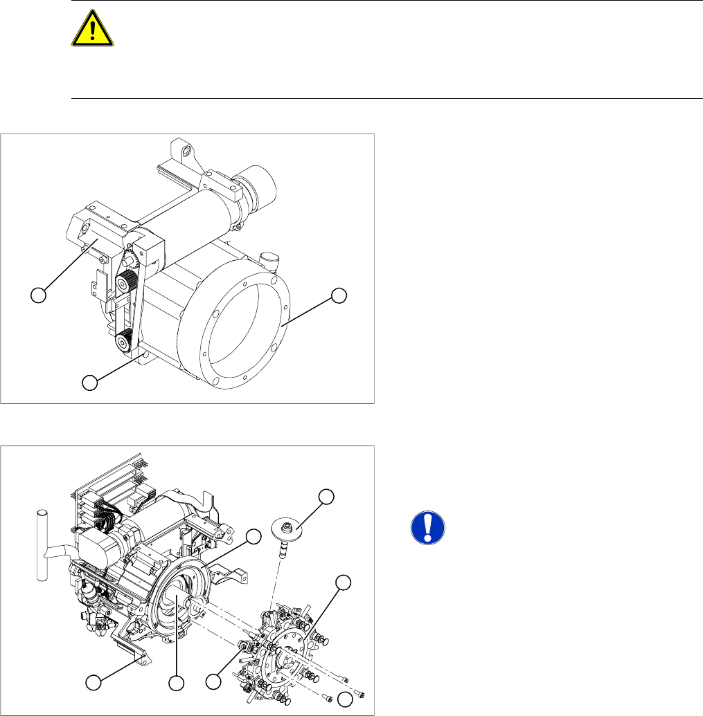
Legend
1. Star drive, digital/ DLM3
2. 4 x M5x16 hexagon socket-head screws
3. C&P head front part
X If you still can not fit the star in the magnetic
neutral position of the star motor, follow the
instructions below:
X Loosen the four M5x16 hexagon socket-head
screws (2) fixing the star drive (1) and turn the
star drive in the direction that will allow the star
to be adjusted with respect to the magnetic
neutral position.
X Tighten the four hexagon socket-head screws.
1
3
2
X Loosen the three M3x8 hexagon socket-head
screws (5) fixing the star again and repeat the
adjustment procedure.
NOTE:
The star is correctly installed, if it does
not turn out of position when the gauge
pin is removed during zero current star
operation.
X Remove the gauge for the star.
X Insert the power cable connector for the star
drive into the slot on the intermediate
distributor. The plug connector is an anti-
rotation connector.
X Fit the front part of the C&P head onto the back
part of the C&P head.
X Check the magnetic neutral position.
1
7
6
5
4
3
2
Service Work
C&P12 Placement Head Replacing the Star [00341181]
184 Service Manual SIPLACE D4
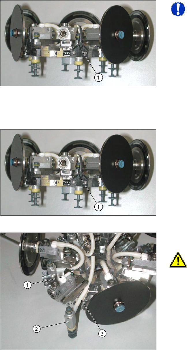
4.5.17.2 Replacing the Air Blast Supply to the Star [03000896-xx]
Removal/Installation
4.5.17.3 Replacing the Silicone Hoses on the Star [00341183S01]
Removal
NOTE: Do not remove the star!
For clarity, the diagram shows the star
when removed from the machine.
However, you do not need to remove
the star to replace the air blast supply.
X Undo and remove the two screws fastening
the air blast supply (1).
X Fasten the air blast supply with the two screws
provided.
X Dismantle the star from the C&P head.
X Remove the sleeve from the segment of the
defective hose.
X Undo and remove the two screws fastening
the air blast supply (1).
X Disconnect the hose (3) from the segment (1).
X Now pull the valve (2) out of the star.
ATTENTION: O-ring
There is an O ring behind the valve.
Make sure that you do not lose this and
that you fit it again during installation!
X Disconnect the hose from the valve.