00195166-0402_SM_D4_EN.pdf - 第195页
Service W ork Checking the Cable Routing C&P12 P lacement Head Service Manual SIPLACE D4 195 4.5.21.4 Running the V alve Positioning Drive Cables Avoid loose cables. The diagram shows the boa rd support to th e side …
Service Work
C&P12 Placement Head Checking the Cable Routing
194 Service Manual SIPLACE D4
4.5.21.2 X Gantry Cable Routing
4.5.21.3 Component Sensor Cable Routing
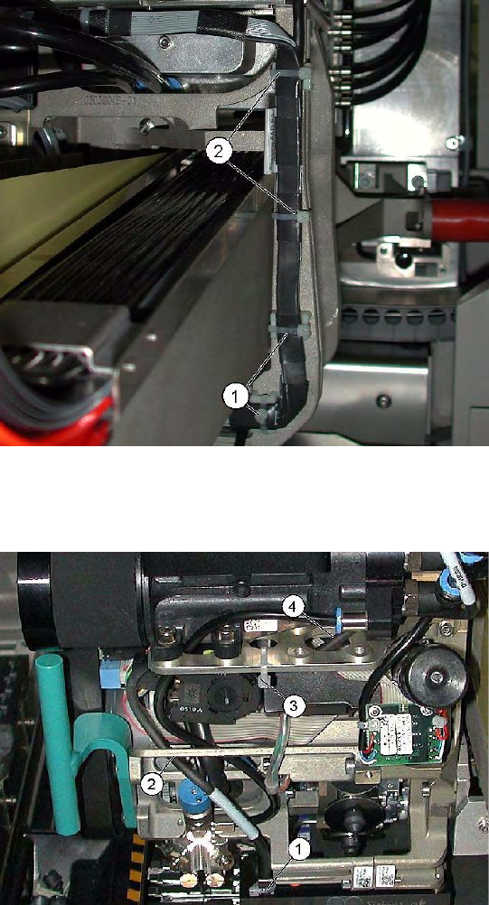
Avoid damage from the Y gantry.
Make sure that the X gantry cables do not touch
the Y gantry.
4 cables ties (1), (2) protect the cables from
damage caused by the Y gantry.
Always use small cable ties, which do not rub
against the gantry.
Avoid loose cables.
The connection cables for the component sensor
must be fixed with a cable tie near to the press-fit
connection, as shown at (1).
The cable is run through the frame openings (2)
and (4).
The cable is held by a cable tie at (3).
Service Work
Checking the Cable Routing C&P12 Placement Head
Service Manual SIPLACE D4
195
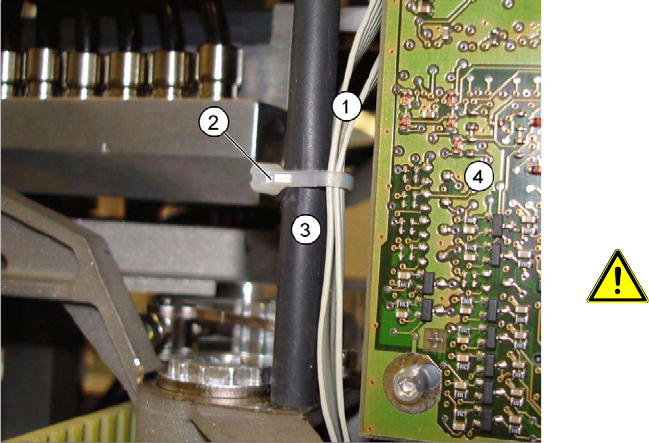
4.5.21.4 Running the Valve Positioning Drive Cables
Avoid loose cables.
The diagram shows the board support to the side
of the placement head and the illumination board
(4) on the component camera.
The connection cables for the valve positioning
drives (1) of the reject and placement circuits need
to be fixed at the bolt of the board holder (3) with a
cable tie (2).
CAUTION: Wrap insulating tape
around bare bolts
If the bolts are not already covered with
a plastic hose, as shown here, wrap
insulating tape around the fixture point.
Service Work
C&P12 Placement Head Press Fit Connections with Fixture Clips on the Vision Board (D Series)
196 Service Manual SIPLACE D4
4.5.22 Press Fit Connections with Fixture Clips on the Vision Board (D Series)
4.5.23 Replacing the Raceway (Circular Arc Guide)
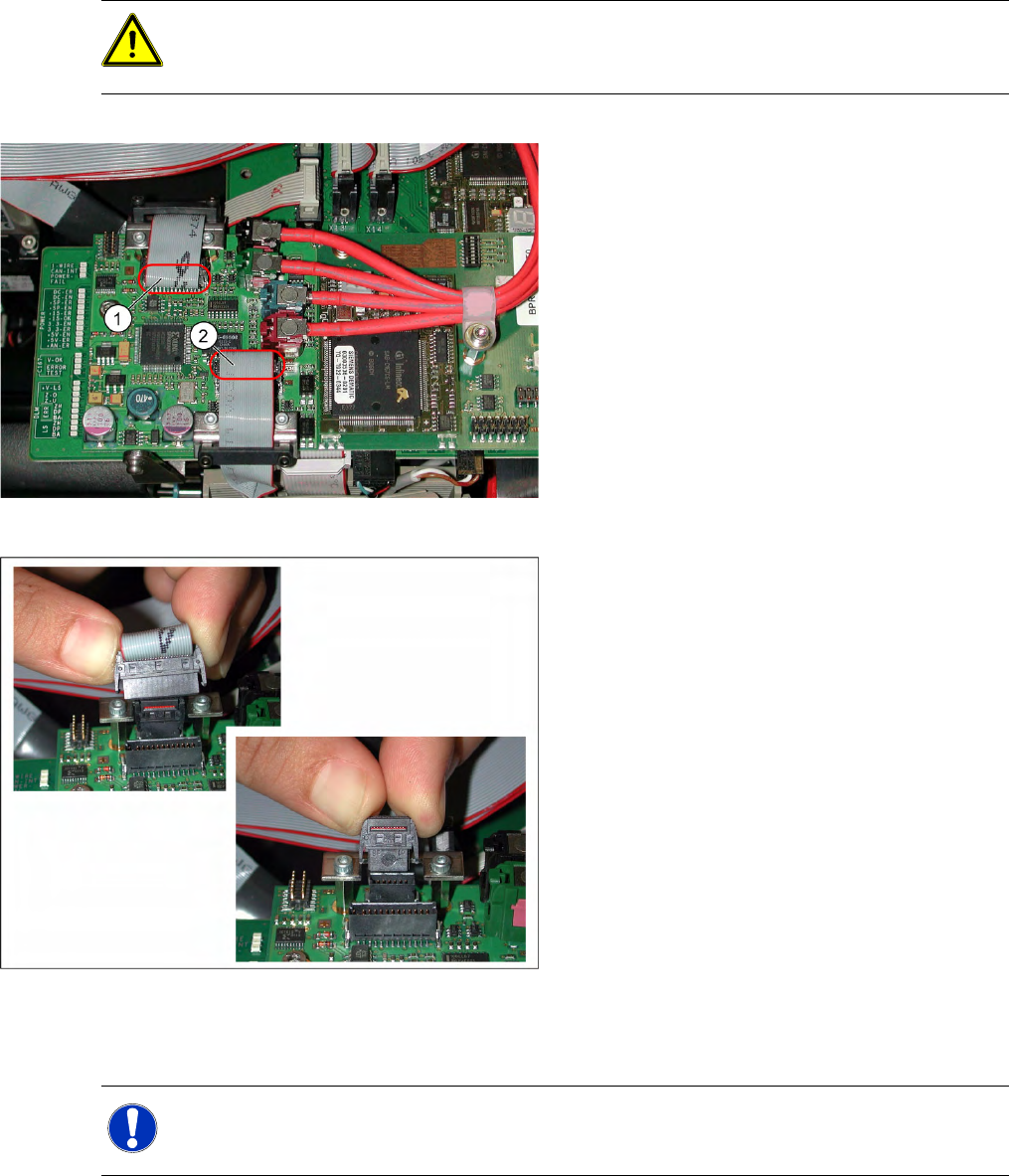
ATTENTION: Do not damage the fixture clips!
To disconnect the component and PCB camera connections, you need to open the fixture clips
by applying pressure to the side of the connector.
The adjacent diagram shows the press-fit
connections for the component camera (1) and the
PCB camera (2) on the Vision board of the
SIPLACE D1/D2. Each of the two positions has
two connectors of different sizes with fixture clips.
Z To release the press-fit connections, press the
connector sides together at the top, with your
thumb and index finger.
X The fixture clips will open and the connector
can be pulled up and off.
> The adjacent diagram shows the two press-fit
connections arranged one above the other, for
the Vision signals (small connector) and
illumination control (large connector) after
disconnection of the connectors.
NOTE:
This service task may only be performed by specially trained SIPLACE service technicians.
The procedure is described in a separate manual.