00195166-0402_SM_D4_EN.pdf - 第20页
Overview Electrical System Position of the module s 20 Serv ice Manual SIPLACE D4 3.2 Electrical System 3.2.1 Position of the modules 3-5: Position of the modules Legend 1 Power supply unit 6 Sector 2 2 Axis unit for pla…
Overview
SIPLACE D4 D-Series - General
Service Manual SIPLACE D4
19
3.1.4 SIPLACE D4
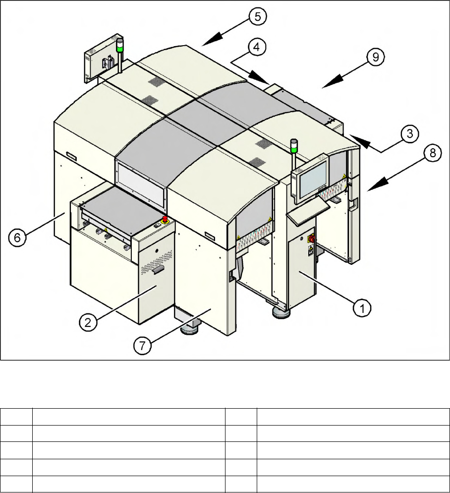
3-4: SIPLACE D4 with four gantries
Overview
4 gantries
4 placement heads
– 4 x C&P12
Component spectrum: 01005 – 18.7 x 18.7
mm
Placement performance: up to 60,000
components per hour
Placement accuracy: up to 60 µm at 3 sigma
Placement force: 2.4 N to 5 N
5-part conveyor with bumper function
Locations:
– 144 x 8 mm (3 x 8 mm)
For more details, refer to the D4 specifications.
Overview
Electrical System Position of the modules
20 Service Manual SIPLACE D4
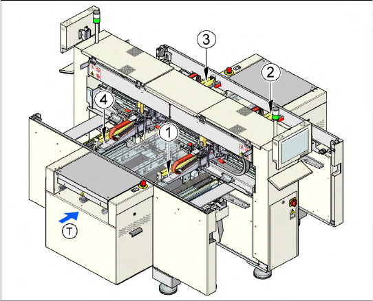
3.2 Electrical System
3.2.1 Position of the modules
3-5: Position of the modules
Legend
1 Power supply unit 6 Sector 2
2 Axis unit for placement areas 2 + 3 7 Sector 3
3 Computer unit 8 Sector 4
4 Axis unit for placement areas 1 + 4 9 Transport direction
5Sector1
Overview
Power Supply Unit Electrical System
Service Manual SIPLACE D4
21
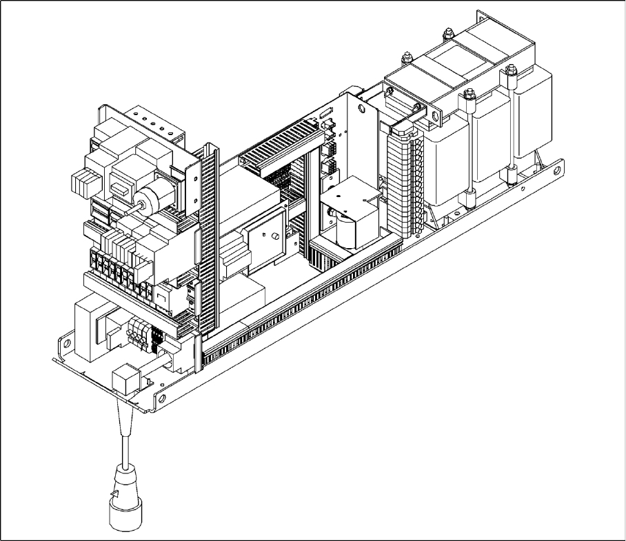
3.2.2 Power Supply Unit
3-6: Power supply unit
The power supply unit is located in the left of the central machine section. A lockable door prevents
access to the unit.
3.2.2.1 Supply Voltages
The power supply unit provides the following supply voltages:
200 V for the servo amplifier of the X and Y axes in the axis unit
100 V- / 4 V- for the servo amplifier of the star in the axis unit
30 V for the servo amplifier of the Z and DP axes in the axis unit
52 V- for the DC/DC converter in the distributor of sector 1
40 V for the changeover tables and the PCB handling system
8 V for the changeover tables
3 x 230 VAC for the lifting table motors of the single or dual conveyor (option)
230 VAC for the UPS for the station computer and monitors