00195166-0402_SM_D4_EN.pdf - 第212页
Settings Gantry Travel Ranges and Speed Monitor ing (A364) 212 Serv ice Manual SIPLACE D4 6.2 Gantry 6.2.1 T ravel Ranges and S peed Monitoring (A364) The travel range of the X and Y ax es will be de termined automatical…
Settings
Checking the Firmware Function Electrical System
Service Manual SIPLACE D4
211
6Settings
The electrical assemblies are in part set via jumpers or DIP switches. The following tables provide a brief
overview of the electrical settings. For details, please consult the setting instructions.
6.1 Electrical System
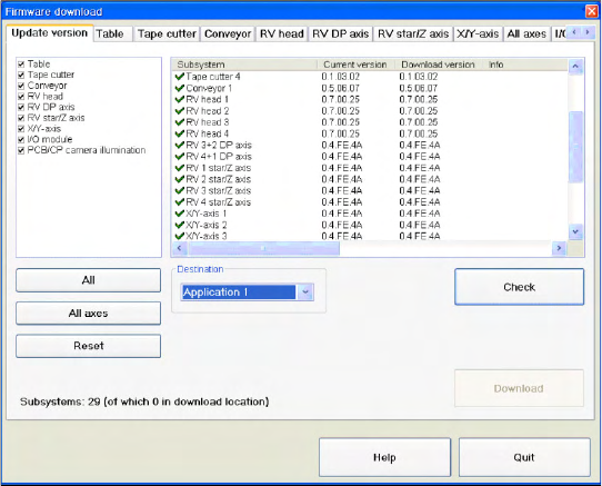
6.1.1 Checking the Firmware Function
6.1.2 Firmware Download Note
From the following station software versions, the firmware download can be performed to all CAN bus
nodes, via the standard SITEST interface.
505.04 SP2
603.01 SP1
604.01 SP1
X Select a
Target
(BIOS/application 1/
application 2) and click on the
Check
.
Settings
Gantry Travel Ranges and Speed Monitoring (A364)
212 Service Manual SIPLACE D4
6.2 Gantry
6.2.1 Travel Ranges and Speed Monitoring (A364)
The travel range of the X and Y axes will be determined automatically with the SITEST program.
This means that, during travel range calibration, the axis concerned moves as far as possible towards
the minimum or maximum position, until the set target value is no longer reached by the axis card. It is
then assumed that the hardware limit switch (bumper) has been reached. In a time window of approx.
10 ms, the greatest actual value achieved is taken to calculate the travel range.
To guarantee an appropriate safety gap before the hardware end switch is touched, a certain distance
is deducted from the set travel range. This enables the axis to brake in time, even when errors occur.
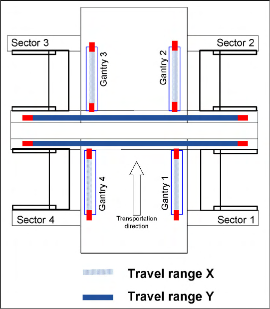
6-1: Travel range for X and Y axes (D4 and X4 shown here)
The end of the X axis travel range is + or -
0.5 mm before the software limit switch, which is
1.5 mm before the bumper. A safety distance of
2.0 mm to the bumper is adequate, if the X axis
moves into this area with excessive speed.
The end of the Y axis travel range is + or -
2.0 mm before the software limit switch. The Y
axis travel range for a particular placement area is
monitored in one direction by the software limit
switch and a bumper. In the other direction, there
is a permanent exchange of communication
between the axes and their positions, via the SPI
Bus (see description of the anticrash function).
Settings
Anticrash Function for the A364 Axis Card Gantry
Service Manual SIPLACE D4
213
6.2.2 Anticrash Function for the A364 Axis Card
6.2.2.1 Anticrash Function for the A364
The anticrash function is no longer provided by the anticrash board but instead by the A364 software
(application 1). This means that the proximity switches used to monitor the travel range and the
sensor for monitoring the gantry spacing are no longer required.
Tasks:
– Monitoring the X and Y axis travel ranges
Evaluation of the actual position of the respective axis in the direction of the bumper, based on
the speed.
– Monitoring the distance of both Y axes in a placement area
Evaluation of the actual position of the own gantry and the partner gantry plus the respective
speed at gantry crash monitoring.
– Axis count error
Monitoring incoming count pulses (edge control) over time.
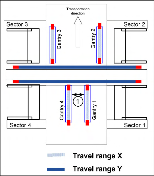
6-2: Travel range for X and Y axes (D4 and X4 shown here)
Legend
1. During travel range calibration, the X axis
moves as far as possible towards the
minimum or maximum position, until it touches
the bumper.
The travel ranges are calculated, taking into
account the relevant safety gap.
2. In placement areas 1 and 2, gantry 1/2 moves
to the minimum position and gantry 4/3 to the
maximum position, for calculation of the Y axis
travel range .
3. The minimum safety distance between the
gantries, during placement: minimum 4 mm.