00195166-0402_SM_D4_EN.pdf - 第215页
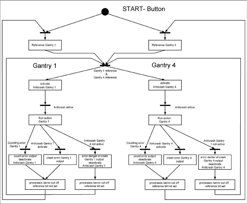
Settings Anticrash Function for the A364 Axis Card Gantry Service Manual SIPLACE D4 215 6.2.2.5 Anticrash Function - Procedure 6-3: Example of the sequence for the anticrash function in placement area 1
Settings
Gantry Anticrash Function for the A364 Axis Card
214 Service Manual SIPLACE D4
6.2.2.2 Anticrash Monitoring for the A364
The anticrash function is activated after the X/Y axes have been referenced. When the gantry axes are
referenced for the first time, anticrash monitoring will not be active, which is not so important, due to the
low reference speed.
After this, the bit is set for the anticrash monitoring function and the actual position for the relevant
partner gantry is continuously communicated via the SPI Bus.
The following information is exchanged between the Y axes:
Actual position of the own gantry
Gantry speed
Status information (reference state, anticrash monitoring state ).
6.2.2.3 Error "Gantry Crash"
A “gantry crash” error is established by calculating the position difference and speed difference for both
axes. A gantry crash error is signaled via the axis card and the CAN Bus. The servo is released for both
axes and both need to be referenced again.
6.2.2.4 Count Error:
If the axis board detects a "fatal count error", the axis concerned will be released and the anticrash
function disabled. The other axis is informed of this in the status information and will also disable the
anticrash function. The released axis now needs to be referenced again.
after which the anticrash function will be re-enabled for both axes.
Settings
Anticrash Function for the A364 Axis Card Gantry
Service Manual SIPLACE D4
215
6.2.2.5 Anticrash Function - Procedure
6-3: Example of the sequence for the anticrash function in placement area 1
Settings
Gantry Description of the PCB boards on the Gantry
216 Service Manual SIPLACE D4
6.2.3 Description of the PCB boards on the Gantry
The boards on the gantry described below are basically identical and do not depend on the head
configuration of D1, D2 and D4 machines (the D3 has a different board here). The CAN bus terminating
resistor is fixed onto the gantry head distributor.
6.2.3.1 Gantry Head Distributor
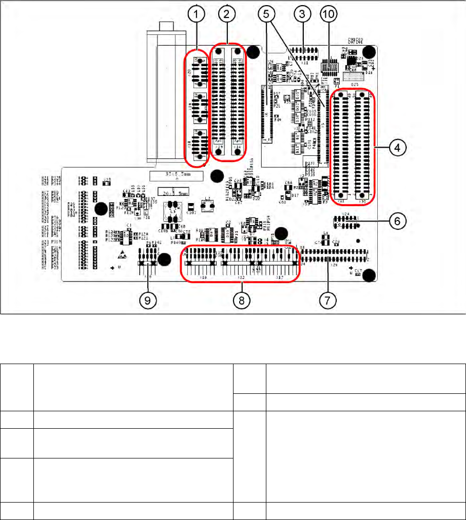
6-4: Gantry head distributor (from above)
Legend
1 X20 stepping motor for reject position
X19 stepping motor for pickup/place
X18 stepping motor for swiveling in the DP axis
6 X24 Test connector for „digital track signals for
X-axis“
7 X29 connector for Vision board
2 X13/X14 flat ribbon cable to C&P head 8 X10 Connector vacuum measurement board
X12 DP axis motor
X16 Reference proximity switch (nor used)
X17 X-axis end position proximity switch (not
used)
X22 Temperature feeler
X21 Free (not used)
3 X11 test connector for CAN Bus, SPI Bus,
RS232
4 X30/X31 flat ribbon cable to P&P head for D1
(D4 not in use)
5 X5/X6 connector for 16 bit processor (TQM) 9 X26 connector for CO sensor