00195166-0402_SM_D4_EN.pdf - 第22页
Overview Electrical System Power Supply U nit 22 Serv ice Manual SIPLACE D4 3.2.2.2 Description of the power supply functions Position of Protective Cont actor Combination and Service Socket Protective contactor combinat…
Overview
Power Supply Unit Electrical System
Service Manual SIPLACE D4
21
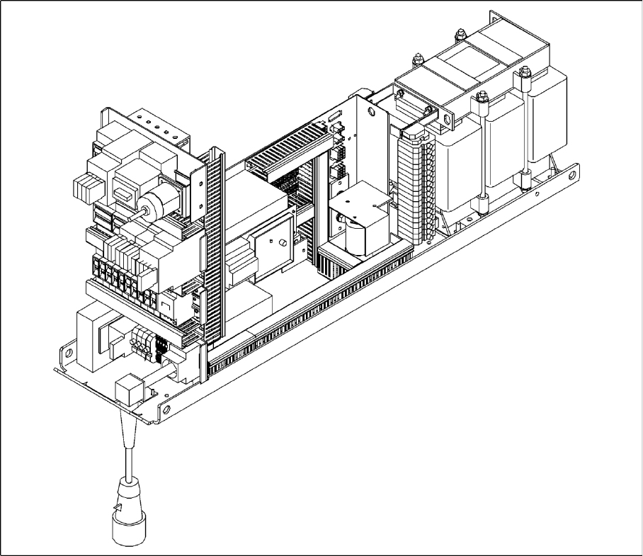
3.2.2 Power Supply Unit
3-6: Power supply unit
The power supply unit is located in the left of the central machine section. A lockable door prevents
access to the unit.
3.2.2.1 Supply Voltages
The power supply unit provides the following supply voltages:
200 V for the servo amplifier of the X and Y axes in the axis unit
100 V- / 4 V- for the servo amplifier of the star in the axis unit
30 V for the servo amplifier of the Z and DP axes in the axis unit
52 V- for the DC/DC converter in the distributor of sector 1
40 V for the changeover tables and the PCB handling system
8 V for the changeover tables
3 x 230 VAC for the lifting table motors of the single or dual conveyor (option)
230 VAC for the UPS for the station computer and monitors
Overview
Electrical System Power Supply Unit
22 Service Manual SIPLACE D4
3.2.2.2 Description of the power supply functions
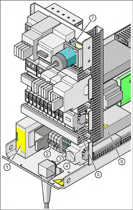
Position of Protective Contactor Combination and Service Socket
Protective contactor combination 3TK2825
The protective contactor combination is contained in the power supply unit. It is used to monitor the
EMERGENCY STOP circuits and safety equipment.
There are three conditions that must be fulfilled in order to activate the protective contactor combination:
The "software enable" signal must have been sent.
The EMERGENCY STOP loop must be closed.
The start button must have been pressed.
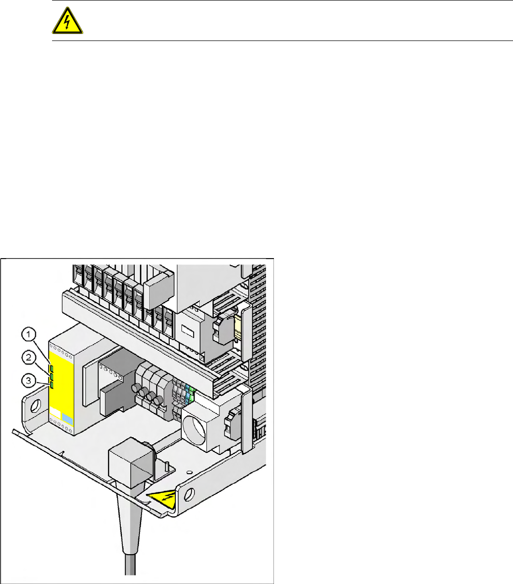
The front side of the protective contactor combination has three green LEDs for displaying the
operational mode:
The "Power" LED indicates that voltage is present.
The "Channel 1" and "Channel 2" LEDs light up if the start button has been pressed, the
EMERGENCY STOP loop is closed and the signaling circuit is not signaling a fault status.
3-7: Position of protective contactor combination and service socket
Legend
1. Protective contactor combination K1
2. Fuses FU, FV, FW, FBU
3. Infeed terminal X1
4. BU1 service socket
5. Z2 reactor
6. Main power filter Z1
7. S1 main power switch
Overview
Power Supply Unit Electrical System
Service Manual SIPLACE D4
23
Service socket
The service socket is located in the power supply unit and is protected by the cover. It can only be used
if the placement system is connected to the main power supply via a 5-wire connection (L1, L2, L3, N,
and PE). If a 4-wire connection is used, e.g. without N, the socket cannot be used.
EMERGENCY STOP Loop and Signaling Circuit
Structure of the EMERGENCY STOP loop
The following contacts are connected in series and form the EMERGENCY STOP loop:
normally open (NO) contacts for the four protective cover switches
normally open (NO) contacts in the two protective switches for the cover flaps over the PCB conveyor
Normally open (NO) contacts for the two EMERGENCY STOP buttons
normally open (NO) contacts for the four component trolleys
normally open (NO) contacts for the four flaps over the push-buttons for raising the CO tables
channels 2 and 3 of the protective contactor combination K1
If the EMERGENCY STOP loop is closed, 24 VDC is present at channels 2 and 3 of the PCC. The two
green LEDs for channels 2 and 3 light up in addition to the green Power ON LED.
DANGER:
Observe the safety instructions for lethal voltages, even when the machine is switched off.
3-8: Signal LED on the protective contactor combination
Legend
1. Power
2. Channel 1
3. Channel 2