00195166-0402_SM_D4_EN.pdf - 第220页
Settings Gantry Checking the DIP Switche s 220 Serv ice Manual SIPLACE D4 6.2.4 Checking the DIP Switches 6.2.4.1 DIP Switch on Gantry Head Distributor * Not all gantries may be available, depending on the machine type. …
Settings
Description of the PCB boards on the Gantry Gantry
Service Manual SIPLACE D4
219
6.2.3.2 Vision Board (Digital)
The Vision processor board is mounted on the gantry head distributor board. This PCB is used for all
four gantries.
See also:
J
6.2.4.2 DIP Switch on Vision Board [
J
220]
6.2.3.3 CAN 16 bit processor board (TQ module)
Description of 7-segment display (normal operation "." flashes):
After switch ON the machine appears " 0 " on the display
Display "b" --> BIOS was started.
Display flashes alternatively between "b" and "." --> no application available or unable to start
application.
Display " -I " and " I- " application was loaded.
"." flashes on the display --> ready for operation.
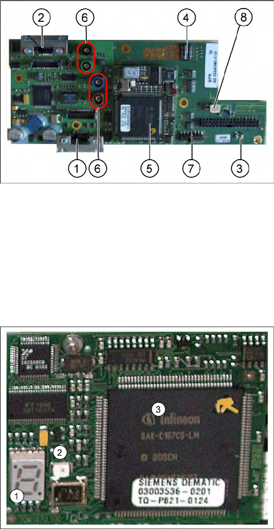
6-6: Vision board
Legend
1. X8 Connector illumination and video signals
PCB camera
2. X3 Connector illumination and video signals
component camera
3. LEDs P15V - 15Volt / Vcc - Power supply
Vision board
4. DIP switch
5. CAN processor 16 bit (TQM module)
6. Connector X22 - X25 - Connectors for the
video cable to the trailing cable
7. Connector X11 for download
8. Voltage supply 11 VDC, measurable
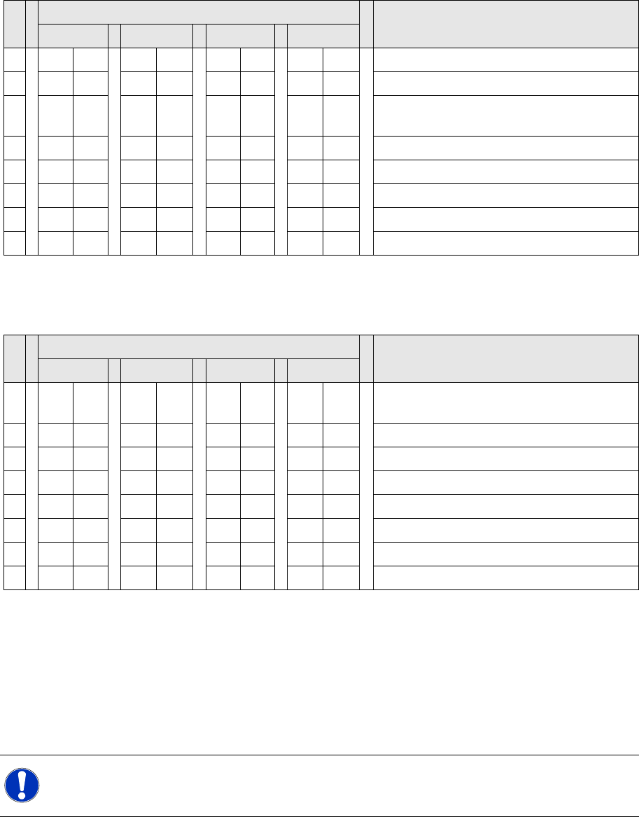
6-7: 16 bit processor (TQ module)
Legend
1. 7 Segment display
2. LED for manual RESET of processor
3. 16 bit processor
The 16 BIT CAN processor is used for various
different functions in the following units:
(see chapter communication and control too)
Visionboard, communication and control via
the CAN Bus to the Vision computer.
Gantry head distributor, control of head
processes and vacuum
Settings
Gantry Checking the DIP Switches
220 Service Manual SIPLACE D4
6.2.4 Checking the DIP Switches
6.2.4.1 DIP Switch on Gantry Head Distributor
* Not all gantries may be available, depending on the machine type.
6.2.4.2 DIP Switch on Vision Board
* Not all gantries may be available, depending on the machine type.
6.2.5 Mechanical Adjustment of the Incremental Encoder
The incremental encoders (read units) on the X and Y axis are adjusted exactly to the position of the
incremental scale. The two limit marks on the incremental encoder show where the top/bottom positions
of the scale should be. The encoder is also mechanically set to a distance of 0.4 mm +/- 0.1 mm to the
incremental scale.
After this adjustment of the incremental encoder you have to check the zero pulse and track signals.
Correct installation should ensure correct count and zero pulse signals. For troubleshooting purposes
(error analysis and fixing), you will need to measures these signals with the oscilloscope. (See service
manual.)
S Setting for gantry* Comments
1 2 3 4
1 OFF ON OFF ON P0 – gantry ID0 address switch 1 --> gantry
2OFF OFF ON ONP1 – gantry ID1 address switch 2 --> gantry
3 OFF OFF OFF OFF S1 – switch for DLM head (delay switching on
LB down – Z-axis)
4 OFF OFF OFF OFF BL – Enable boot loader for serial port
5 OFF OFF OFF OFF Reset - CAN processor 16 Bit (TQM module)
6 OFF OFF OFF OFF C0 – no current function
7 OFF OFF OFF OFF C1 – no current function
8 OFF OFF OFF OFF S2 – switch for DLM head (no current function)
S Setting for gantry* Comments
1 2 3 4
1 OFF OFF OFF OFF Boot mode - CAN processor 16 Bit via
connector X11
2 OFF OFF OFF OFF Reset - CAN processor 16 Bit to subboard
3 OFF ON OFF ON P0 - Address switch 1 --> Gantry
4OFF OFF ON ONP1 - Gantry address switch 2
5 OFF OFF OFF OFF WPE - Write protect enable, currently OFF
6 OFF OFF OFF OFF CAN R - Switch terminator CAN bus
7ONONONONTest 1 - CAN 1 MBit/s --> ON
8ONONONONTest 0 - CAN IDs --> ON
NOTE:
To set this distance, use one or more small plastic disks with a total thickness of 0.4 mm.
Settings
Calibrating the C&P Head and Cameras C&P12
Service Manual SIPLACE D4
221
6.3 C&P12
6.3.1 Calibrating the C&P Head and Cameras
Automatic calibration of all heads and cameras
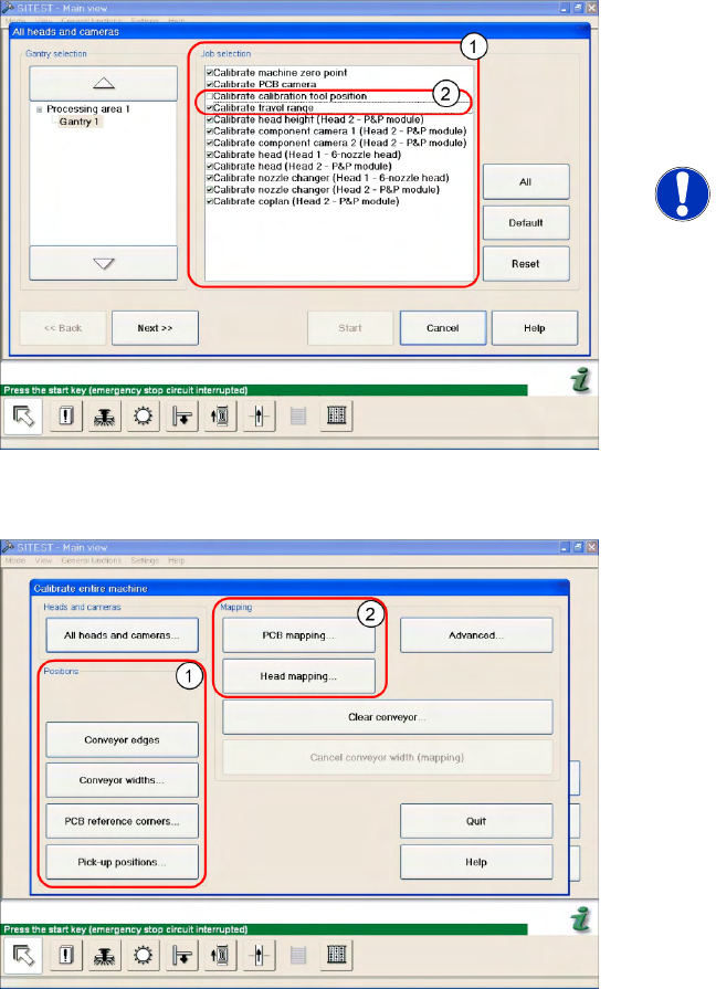
6-8: The menu may vary, according to the machine type and configuration.
X In the SITEST menu, select
Calibrate Entire
Machine
-->
All Heads and Cameras
to open
the adjacent menu.
X In
Job Selection
(1) , select the components
to be calibrated.
NOTE:
These two entries (2) are optional.
X To continue calibration with manual handling,
select the four consecutive menus in Section
Positions
(1) and the two menu items in the
Section
Mapping
(2).