00195166-0402_SM_D4_EN.pdf - 第223页
Settings Boards at C&P12 C&P12 Service Manual SIPLACE D4 223 6.3.2.2 LEDs on gantry head distributor Legend Display functions and signals: 1. CAN signal 2. Power supply 3. Head Processo r 4. LEDs C&P12 6.3.2.…

Settings
C&P12 Boards at C&P12
222 Service Manual SIPLACE D4
6.3.2 Boards at C&P12
All the settings described in this chapter are head-specific and apply here for the C&P12.
6.3.2.1 8-fold DIP Switch of the gantry head distributor (incl. switch S1) – C&P6/12
Switch P0 and P1:
Switch S1:
ON – Test mode (without delay)
OFF – Default state (with delay of 3.6 ms+/- 300 us) means: Z axis moves downwards, the top LB is
released and the LB down is enabled after a delay of 3.6 ms.
See also:
J
Description of LEDs on the Gantry Head Distributor [
J
218]
J
6.2.3.1 Gantry Head Distributor [
J
216]
J
6.3.2.2 LEDs on gantry head distributor [
J
223]
DIP switch Switch position Designation
1 OFF P0 (see below)
2 OFF P1 (see below)
3 OFF "S1" for test mode (see below)
4 OFF BL – Enable boot loader for serial port
5 OFF Res (Reset) – CAN processor 16 bit (TQ module)
6 OFF C0 – no current function
7 OFF C1 – no current function
8 OFF S2 – switch for DLM head (no current function)
S Gantry 1 Gantry 2 Gantry 3 Gantry 4 Designation
1 OFF ON OFF ON P0
2 OFF OFF ON ON G1
Settings
Boards at C&P12 C&P12
Service Manual SIPLACE D4
223
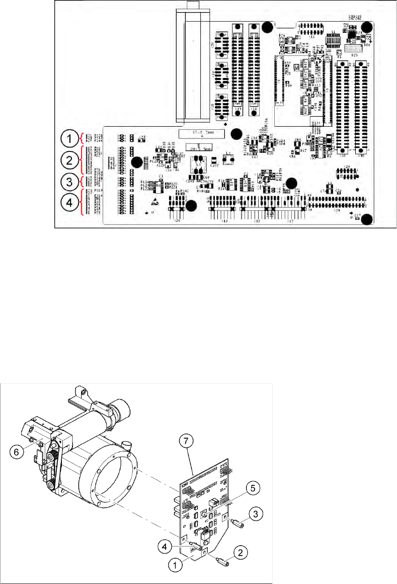
6.3.2.2 LEDs on gantry head distributor
Legend
Display functions and signals:
1. CAN signal
2. Power supply
3. Head Processor
4. LEDs C&P12
6.3.2.3 SP_12 Digital Intermediate Distributor [00330648-05]
6-9: Intermediate distributor
Legend
1. Intermediate distributor
2. Spacer bolt M3x10
3. Spacer bolt M3x10
4. Spacer bolt M3x10
5. Spacer bolt M3x10
6. Front section of C&P head
7. Connectors X1 and X2 (on the rear side)
The intermediate distributor (1) is fixed to the front
part (6) with four spacer bolts (items 2, 3, 4 and 5).
The pressure sensor is located above the spacer
bolts (5), on the back of the intermediate
distribution board. The cover of the intermediate
distributor is fixed with push buttons.
Settings
C&P12 Boards at C&P12
224 Service Manual SIPLACE D4
The following supply voltages and signals are routed by the intermediate distributor to the individual
placement head modules or to the head board:
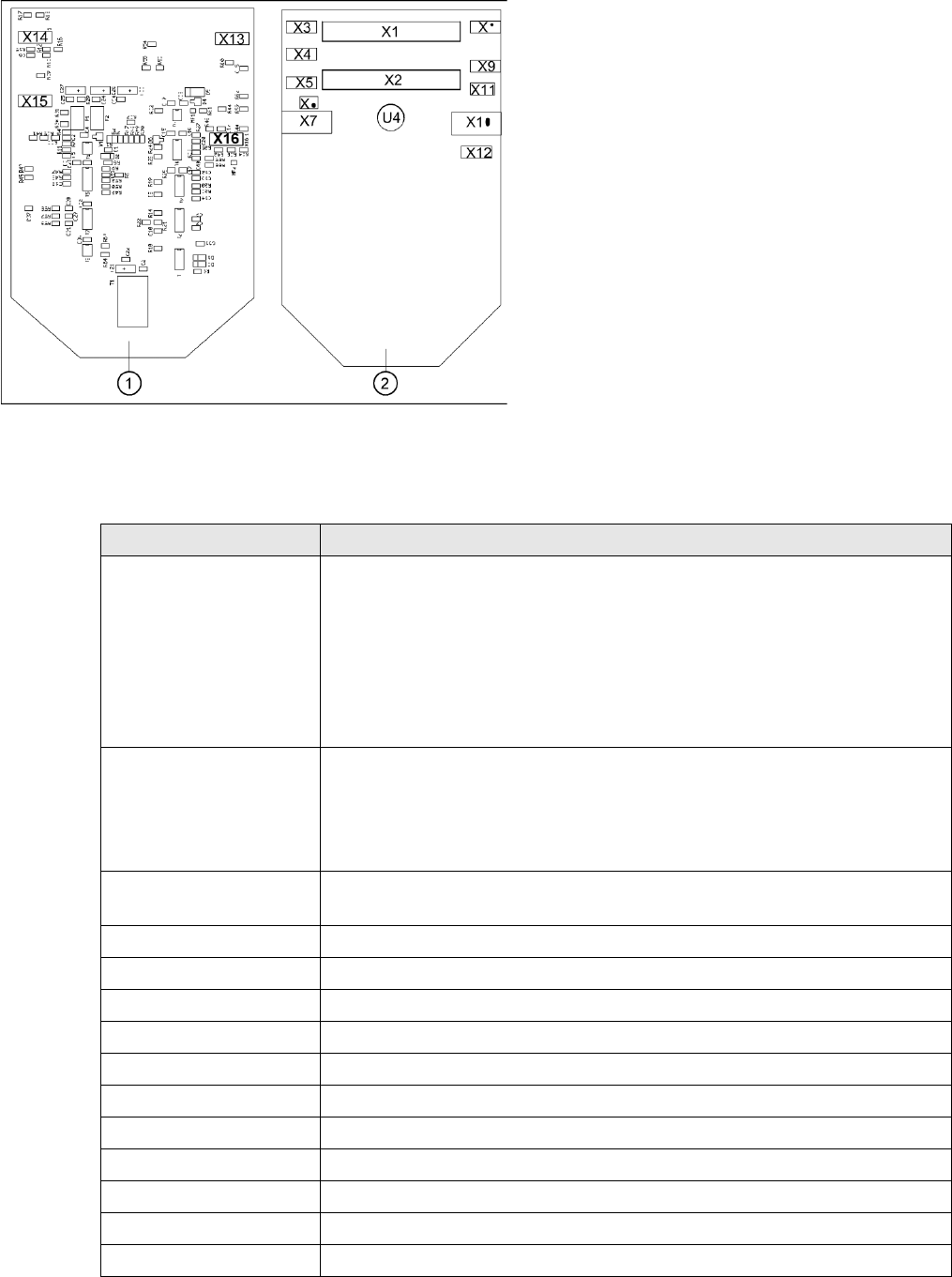
6-10: Position of the sockets
Legend
1. Front of the intermediate distributor
2. Back of the intermediate distributor
U4 = pressure sensor
Two 40-pin ribbon cables run from plug X1 and X2
on the intermediate distributor to socket X14 / X13
on the head board.
Connectors Description
X1, 40-pole Connected to plug X14 on the head board
Voltage supply, tacho and track signals for the Z axis drive
Signal from light barrier "Z axis in top position"
Signal from light barrier "Z axis in bottom position" (sensor stop signal)
Control signal for the air blast valve
Supply voltage +5 VDC, ±15 VDC
Reference point signal for the DP axis
Track signals for the DP axis
X2, 40-pole Connected to plug X13 of the gantry head distributor
Voltage supply and track signals for the star axis drive
Reference point for the star axis
Analog air blast pressure value
Supply voltages +5 VDC, ±15 VDC, +24 VDC
X3, 10-pole Connection for the Z motor and Z tacho signal (tacho signal is not used on the HF
machine)
X4, 10-pole Connection for the Z axis track signals
X5, 10-pole Connection for the star motor
X6, 6-pole Connection for the air blast valve
X7, 10-pole Connection for the DP axis track signals
X10, 10-pole Connection for the "Z axis up" signal
X11, 8-pole Connection for the light barrier "Z axis down" signal (sensor stop signal)
X12, 10-pole Connection for the star axis track signals
X13, 10-pole Test connection for the Z axis track signals
X14, 10-pole not used
X15, 10-pole Test connection for the star axis track signals
X16, 10-pole Test connection for the DP axis track signals