00195166-0402_SM_D4_EN.pdf - 第241页
Settings Check the gap between the empty-tape baffle, inside a nd the leading edge of the tape deflector. Component Handling Service Manual SIPLACE D4 241 6.4.3 Check the gap between the empty-tape baffle, inside and the…
Settings
Component Handling Tape Cutter Control Unit
240 Service Manual SIPLACE D4
6.4.2 Tape Cutter Control Unit
The jumper for the CAN bus addressing must be set according to the corresponding location in the
machine.
NOTE: Control unit [03006411-xx] is replaced by CAN node module.
This version is replaced by the backwards compatible CAN node [03052027-xx] module.
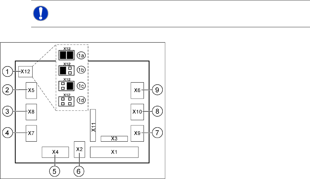
6-24: Jumper setting on the tape cutter unit (example of D4 shown)
Legend
1. X12 – Jumper for location code of cutter:
1a: Gantry 1
1b: Gantry 2
1c: Gantry 3
1d: Gantry 4
2. X5 – Voltage supply to valve (left)
3. X8 – Proximity switch for stroke cylinder out
(left)
4. X7 – Proximity switch for stroke cylinder in
(left)
5. X4 – CAN bus connection
6. X2 – Voltage supply for cutter +24 V and +5 V
7. X9 – Proximity switch for stroke cylinder in
(left)
8. X10 – Proximity switch for stroke cylinder out
(right)
9. X6 – Voltage supply to valve (right)

Settings
Check the gap between the empty-tape baffle, inside and the leading edge of the tape deflector. Component Handling
Service Manual SIPLACE D4
241
6.4.3 Check the gap between the empty-tape baffle, inside and the leading edge of the
tape deflector.
X With the feeler gauge, check:
The distance between the empty-tape baffle and the leading edge of the tape deflector must again
be within the TARGET distance 1.0 to 1.5 mm over the entire length.
If the gap is not OK.
X Loosen the screws holding the empty-tape duct once again and correct the position of the duct in the
holes.
X If this is not enough, you may assume that the cutter was already not in the optimal position before
the empty-tape duct was replaced:
In this case, correct the position of the cutter in the holes of the retaining brackets as described in
section (4.3.2.5 Exchanging the Pneumatic Cutter
J
87 ) .
X Perform the appropriate “Final Steps”.
See also:
J
Tightening Torques for Cutter Screws [
J
87]
J
4.3.2.14 Final Steps [
J
114]
WARNING:
The following check can only be conducted from the bottom of the cutter after it has been
installed in the machine. Wear thick protective gloves;
there is a risk of injury from the blades and the edge of the tape deflector.
NOTE:
For the adjustments it is the best, if a second person is available
CAUTION:
X Tighten the screws to the correct torque.
Settings
Conveyor Adjusting the Tension of the Conveyor Toothed Belt
242 Service Manual SIPLACE D4
6.5 Conveyor
6.5.1 Adjusting the Tension of the Conveyor Toothed Belt
NOTE:
The belt tension is measured at the strand center (i.e. the longest distance between the two
deflection pulleys) .
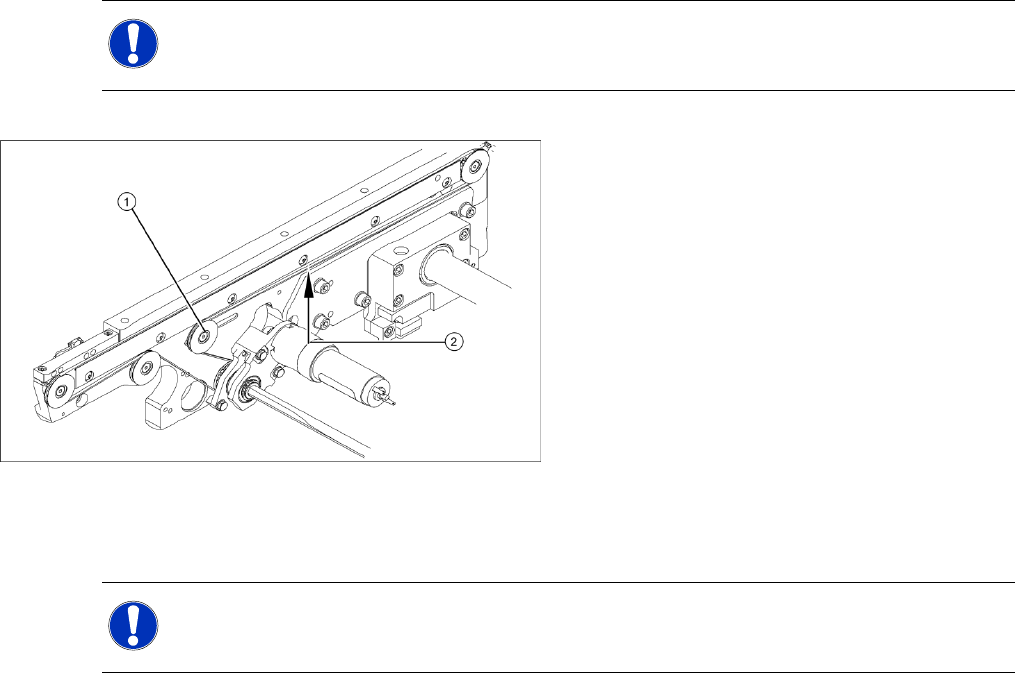
6-25: Measuring and setting the tension of the conveyor toothed belt
Legend
1. Deflection pulley with slot
2. Measuring point of the belt tension measuring
device (strand center )
X Each conveyor section contains a deflection
pulley (1), that can be moved. The tension of
the conveyor toothed belt can be adjusted by
moving this deflection pulley.
X Position the measuring point of the belt
tension device at the strand center (i.e. the
longest distance between the two deflection
pulleys) of the conveyor toothed belt.
X Set the tension of the drive toothed belt
according to the following values.
NOTE:
The tension frequencies per area may vary according to the different belt guides. The belt
tension always remains the same.