00195166-0402_SM_D4_EN.pdf - 第251页
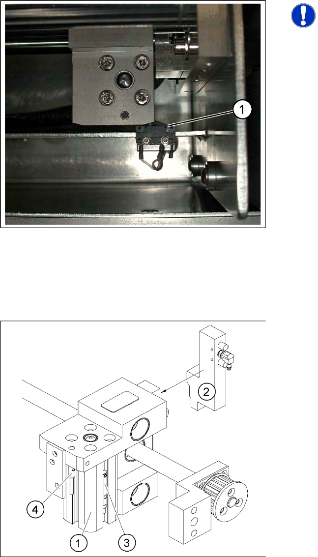
Settings Setting the Laser Light Barrier for the Stopp er Position Conveyor Service Manual SIPLACE D4 251 6.5.5.2 Setting the Pneumatic Cylinder Proxim ity Switch on the Adjustment Unit X Start SITEST X Set any conv eyor…
Settings
Conveyor Width Adjustment Unit
250 Service Manual SIPLACE D4
6.5.4.1 Adjusting the Limit Switch for Initializing the Adjustment Unit
6.5.5 Width Adjustment Unit
6.5.5.1 Setting the Proximity Switch on the Adjustment Unit
X When installing the proximity switch, make sure that this is level with the adjustment unit housing.
X The switching point is set via the actuator on the conveyor side.
X Move the adjustment unit under the conveyor side, then loosen the actuator using the screw.
X Place the distance gauge 0.2 mm on the adjustment unit, press the actuator against the gauge and
fix with the screw.
X Check the actuators on all conveyor sides and adjust where necessary.
X You then need to calibrate the conveyor sides with the software.
6-32: Limit reference switch for adjustment unit
NOTE:
This setting is only required after
replacing the switch or other error
functions in the width adjustment
reference run.
X Move the adjustment unit for the width
adjustment by hand (via the toothed belt) to
the conveyor side.
X Loosen the two screws on the limit switch (1).
X Move the limit switch in the slot towards the
adjustment unit and make sure that the limit
switch is safely switched on.
X Check the switching state of the
corresponding LED (H11 for TSP 201) (H41
for TSP 301) in the conveyor control software.
X Fit the limit switch in this position.
X Calibrate the conveyor width via the SITEST
program.
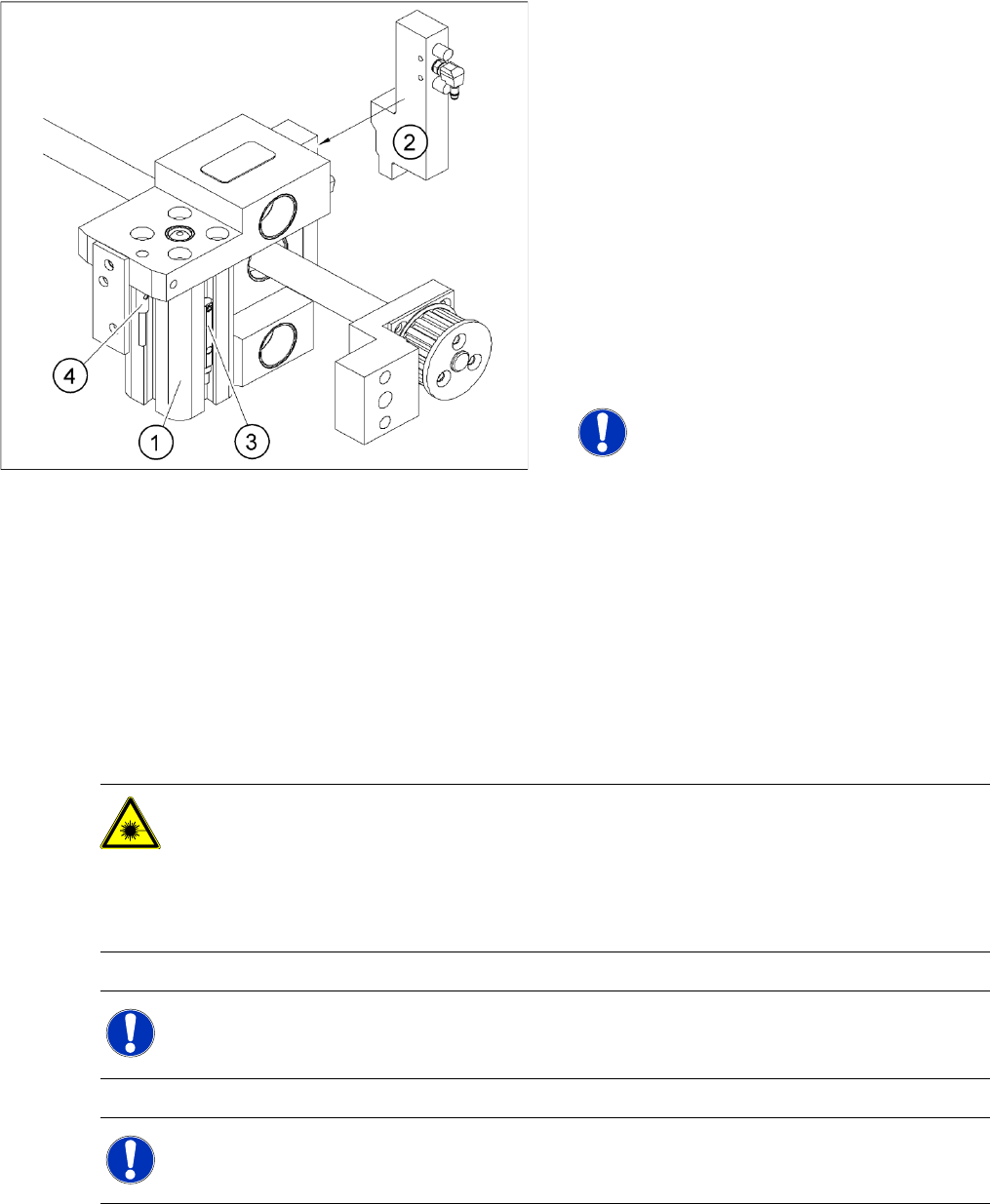
6-33: Overview of the proximity switches on the width adjustment unit
Legend
1. Short-stroke cylinder
2. Solenoid valve
3. Proximity switch for pneumatic cylinder (for
"locking pin up" recognition)
4. Proximity switch for adjustment unit (for
conveyor side recognition)
The proximity switch (3) serves as a signal for
controlling the pneumatic valve of the
adjustment unit. Once the switching point
"conveyor side present" has been reached,
the conveyor side is connected via the
pneumatic valve.
Settings
Setting the Laser Light Barrier for the Stopper Position Conveyor
Service Manual SIPLACE D4
251
6.5.5.2 Setting the Pneumatic Cylinder Proximity Switch on the Adjustment Unit
X Start SITEST
X Set any conveyor width. The adjustment units are positioned directly under the conveyor side.
X Start the I/O menu.
X Activate the pneumatic cylinder.
X Set the proximity switch on the pneumatic cylinder so that the LED (H35/H37 for TSP 301) (H64/65
for TSP 201) shines when connected.
6.5.6 Setting the Laser Light Barrier for the Stopper Position
6-34: Overview of the proximity switches on the width adjustment unit
Legend
1. Short-stroke cylinder
2. Solenoid valve
3. Proximity switch for pneumatic cylinder (for
"locking pin up" recognition)
4. Proximity switch for adjustment unit (for
conveyor side recognition)
The proximity switch (3) on the adjustment unit
cylinder should operate when the adjustment
unit pin is pushed out by the pneumatic
cylinder and therefore connected to the
conveyor side. This signal enables the width
adjustment motor.
NOTE:
The proximity switch on the pneumatic
cylinder is set in its engaged state.
The proximity switch is off when the
cylinder extended into free space.
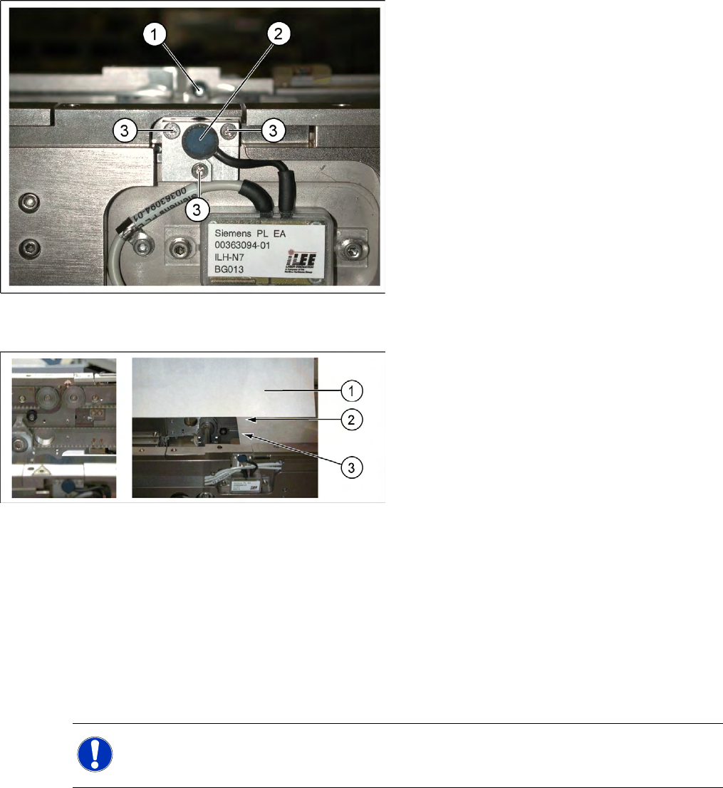
DANGER: Laser class 2
The laser light barrier transmitter emits class 2 laser beams. You do not need to take additional
protective measures!
X You should still never look into the laser beam.
X Adjust the LASER diode bean direction only from the rear side of the LASER (left machine
side).
NOTE:
The laser beam deflection has greatest effect at the maximum conveyor width, it should always
be calibrated at the maximum conveyor width.
NOTE:
After setting the laser light barrier you must check or re-teach the PCB reference corner!
Settings
Conveyor Setting the Laser Light Barrier for the Stopper Position
252 Service Manual SIPLACE D4
Procedure
X Set the maximum conveyor width.
X Choose General functions --> Cycle mode --> Safety mode switch on.
X Activate the relevant laser diode using the input/output functions in SITEST.
X Check the path of the laser beam by covering the front edge of a board with a white label and moving
it into the placement area.
X With the help of the three setting screws, adjust the laser beam to the center of the receiver.
X Check the PCB reference corner and reteach, if necessary.
6-35: Laser light barrier
Legend
1. Laser receiver
2. Laser diode
3. Setting screws (3x)
6-36: Focussing the laser beam
Legend
1. Paper
2. Visible laser beam
3. Board parallel to laser beam
NOTE:
When you move the paper, the beam must follow along the edge of the PCB as accurately as
possible, with minimal deflection to the left and right.