00195166-0402_SM_D4_EN.pdf - 第259页
Settings Conveyor Control TSP 301 Conveyor Service Manual SIPLACE D4 259 6.5.1 1.2 Setting the Lif ting T able Unit [00358684-05] 6.5.12 Conveyor Control TSP 301 6.5.12.1 Jumper Settings for TSP 301 6-42: Setting the dam…
Settings
Conveyor Lifting Table Functions
258 Service Manual SIPLACE D4
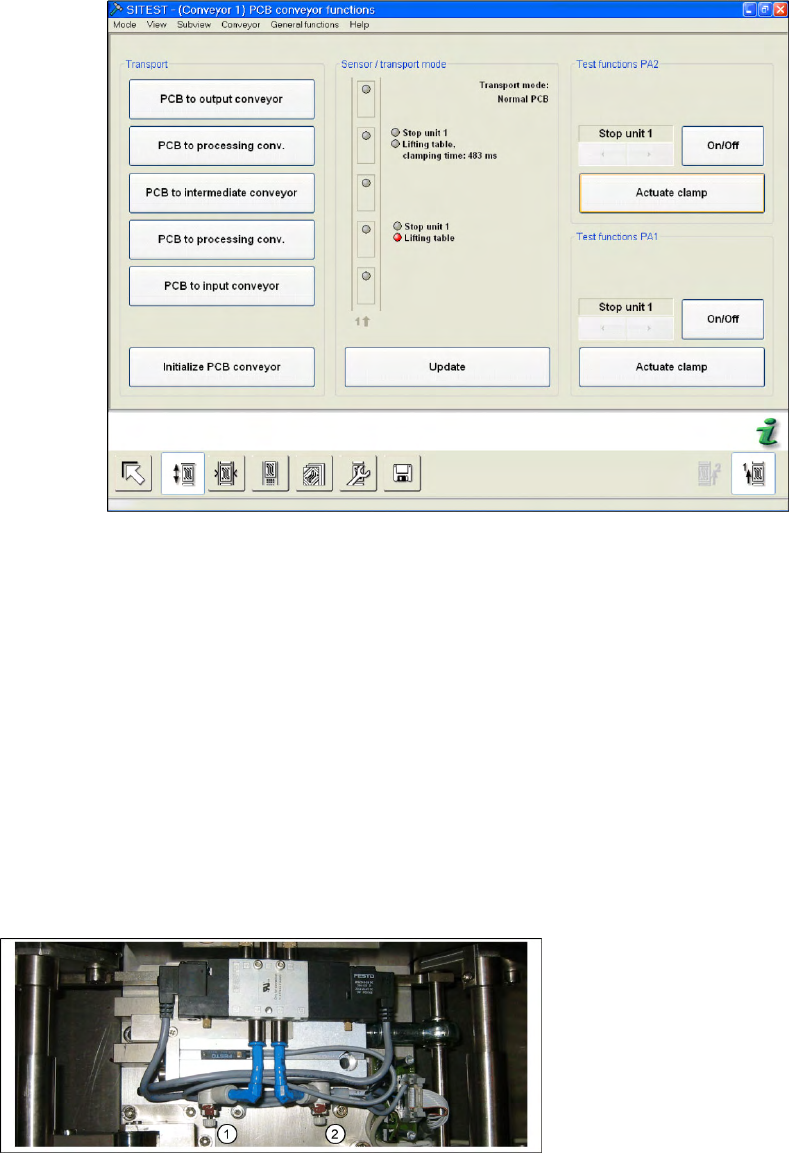
X Switch the machine on and start the SITEST program.
X In the PCB conveyor functions menu (see adjacent diagram) you can see the travel time for the lifting
table (from SW 602 upwards).
X Click on
Actuate Clamp
.
6-41: Time needed to move lifting table down with lifting table plate
X The lifting table will be moved up and the travel time will be displayed (see diagram).
X Press the
Actuate Clamp
button again to move the lifting table downwards and to view the travel
time for the downwards movement.
X If the travel times are not inside the tolerance range or if error messages appear during production,
adjust the travel times (displayed since SITEST 60x) as follows:
X Adjust the valve on the lifting table cylinder, so that you get the following values:
Lifting table up: 500 ms +/-20
ms (without lifting table plate ~450 +/-20 ms DT / ~360 +/-20 ms ET)
Lifting table down: 480 ms +/-20
ms (without lifting table plate ~550 +/-20 ms DT / ~600 +/-20 ms ET)
X If malfunctions occur during the downwards movement or if the board is shaken, reduce the lowering
speed accordingly.
Setting valve anticlockwise: Decrease the lifting table moving time
Setting valve clockwise: Increases the lifting table moving time
Legend
1. (3) adjust valve downwards
2. (4) adjust valve upwards
Settings
Conveyor Control TSP 301 Conveyor
Service Manual SIPLACE D4
259
6.5.11.2 Setting the Lifting Table Unit [00358684-05]
6.5.12 Conveyor Control TSP 301
6.5.12.1 Jumper Settings for TSP 301
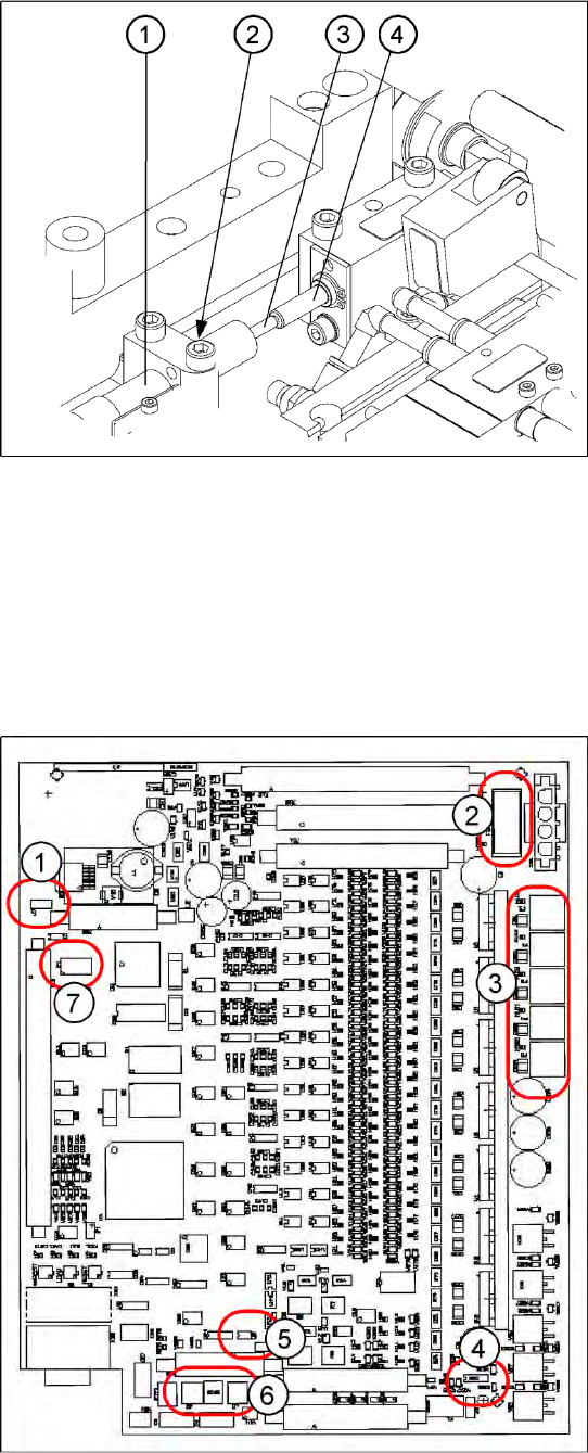
6-42: Setting the damping unit
The damping unit (1) allows the lifting table to
move gently upwards. When the PCB is clamped,
it also prevents excessive bounce by the PCB.
X Check whether the damping unit is fixed with
the locknut (2) in the mounting block and that
the plunger (3) of the damping unit is just
touching the actuator (4). In this default
setting, the lifting table should move up gently.
X If this is not the case, loosen the locknut at the
mounting block and turn the damping unit
approx. one rotation into the mounting block..
X Move the lifting table upwards, with the help of
the software.
X The lifting table should move gently upwards.
The PCB clamping should not engage audibly
and there should be no PCB clamping error
message.
X Check the speed of the lifting table and correct
where necessary.
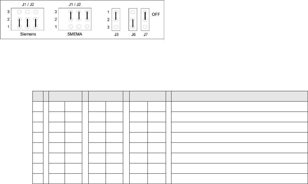
6-43: Jumper positions for conveyor control TSP 301
Legend
1. J7 CAN bus 1 terminating resistor
2. F6 Main Fuse TSP 301
3. F1 - F5 Fuses for the conveyor motors
4. J3 interference loop
5. J6 CAN bus 2 terminating resistor (not used)
6. J2, J1 successor/predecessor station
7. S4 DIL switch
Settings
Conveyor Conveyor Control TSP 301
260 Service Manual SIPLACE D4
*Switches 1-2 set the hardware ID 5 for D4 machines and hardware ID 6 for X machines, HF and D3.
6-44: Jumper J1, J2 "downstream/upstream station" at TSP 301
Legend
J1 predecessor station
J2 successor station
J3 interference loop (emergency stop on
productivity lift switches the placement
machine off)
J6 CAN bus 2 terminating resistor (not used)
J7 CAN bus 1 terminating resistor
S X4I D4 X/D3/HF Comments
1ON ON ONON*
2OFF ON OFF ON* = SIPLACE D4, OFF: SIPLACE X, HF, D3
3OFF OFF OFF OFF= clamping sensor is no longer used
4ONOFFOFFON = X4I, OFF: SIPLACE D4, X, HF, D3
5OFF OFF OFF Not in use
6OFF OFF OFF Not in use
7OFF OFF OFF Not in use
8OFF OFF OFF Not in use