00195166-0402_SM_D4_EN.pdf - 第39页
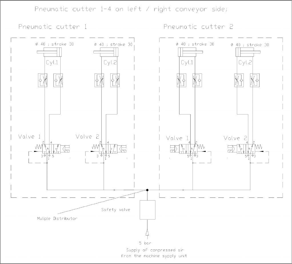
Overview Cutter Component Handling Service Manual SIPLACE D4 39 3.4.2.3 Diagrams of Pneumatic System and Fun ctional Sequence 3-22: Diagram of Pneumatic System: Cutter per conveyo r edge
Overview
Component Handling Cutter
38 Service Manual SIPLACE D4
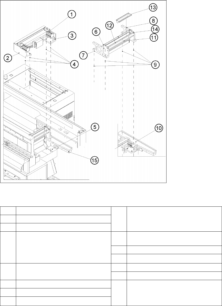
3.4.2.2 Overview: Mechanical Construction
3-21: Overview: of Pneumatic Cutter Version 04 and Empty-Tape Duct Version 03
Legend
*) Loosen these screws only when removing/installing the cutter.
See also:
J
4.3.2.5 Exchanging the Pneumatic Cutter [
J
87]
1 "Pneumatic cutter" 9 Fastening of "empty-tape duct assembly":
2 socket hex head cap screws M 4 x 16 each on
left and right
2 Retaining bracket for cutter, left
3 Retaining bracket for cutter, right
4 Fastening of the cutter,
2 socket hex head cap screws M6 x 25 each on
left and right *)
Re-install any disks or plates that were
previously removed.
10 Mounting surface for the "empty-tape duct
assembly" on the machine base
11 Baffle, inside
12 Baffle, outside
5 Mounting surface for cutter on the machine base 13 Reject box for nozzles
14 Reject box (profile)
6 Empty-tape duct assembly 15 Stop buffer assembly on left and right-hand side
of the machine base,
Fastening: 2 socket hex head cap screws M8
each on left and right
7 Side panel (left) of the empty-tape duct
8 Side panel (right) of the empty-tape duct
Overview
Cutter Component Handling
Service Manual SIPLACE D4
39
3.4.2.3 Diagrams of Pneumatic System and Functional Sequence
3-22: Diagram of Pneumatic System: Cutter per conveyor edge
Overview
Modular Conveyor Module Overview
40 Service Manual SIPLACE D4
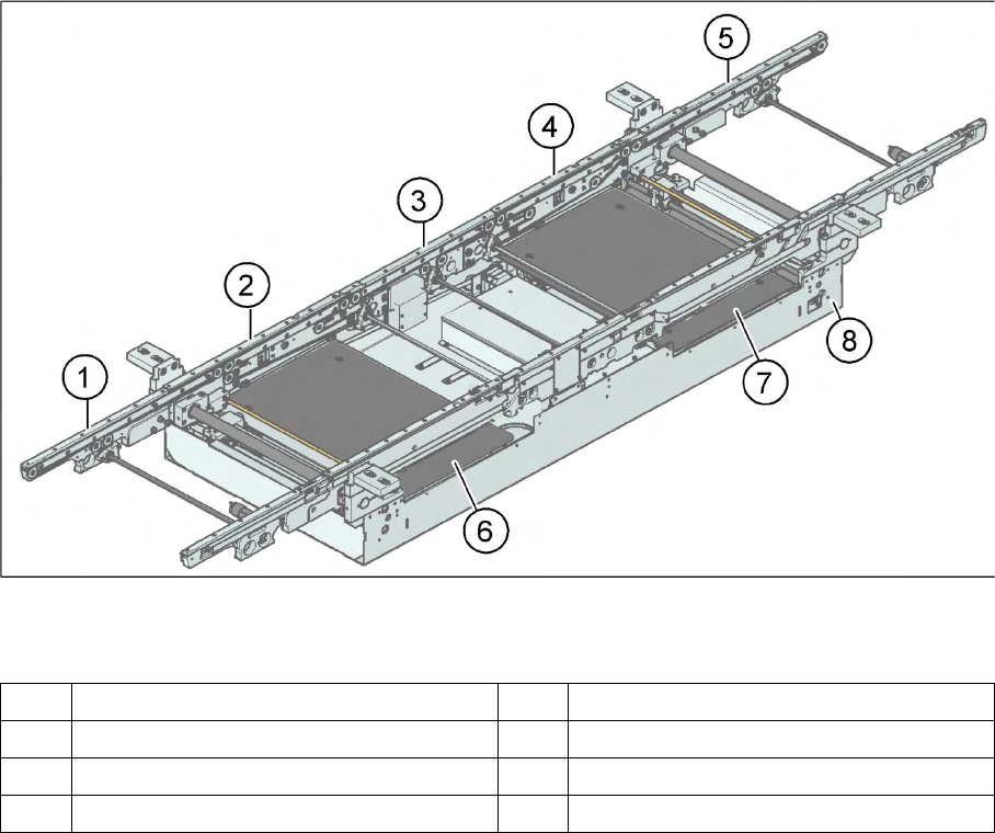
3.5 Modular Conveyor
3.5.1 Module Overview
3-23: PCB conveyor – single conveyor (D3/D4)
Legend
The modular conveyor system consists of an input conveyor, two placement areas, the intermediate
conveyor and the output conveyor. Each conveyor system has automatic width adjustment and a lifting
table to clamp the PCB in place. The standard machine is equipped as a single PCB conveyor. A dual
PCB conveyor system is optionally available. Depending on individual requirements, either the left or
right conveyor side can be selected as the fixed conveyor side.
1 Input conveyor 5 Output conveyor
2 Placement area 1 6 Lifting table placement area 1
3 Intermediate belt 7 Lifting table placement area 2
4 Placement area 2 8 Assembly tray