00195166-0402_SM_D4_EN.pdf - 第51页
Service W ork Measuring the Power Supply Unit Electrical System Service Manual SIPLACE D4 51 4.1.2 Measuring the Power Supply Unit For the po sition of the modules, refer to section (4.1.2.1 Front View J 52 ) . The inp…
Service Work
Electrical System Measuring Voltages on the Power Supply Unit
50 Service Manual SIPLACE D4
4.1.1.3 Preparing the power supply unit for measurement
The power supply unit and main switch are located in the machine base. In front of the unit there is a set
of safety doors which can be opened with the double-bit key.
The unit is fixed to the machine base using an M8 hexagon socket-head screw.
To measure the power supply, proceed as follows:
X Switch the placement system off at the main switch.
X Open the safety doors with the double-bit key.
X Loosen the M8 lock screw, fastening the underside of the unit at the front (see fig).
4-1: M8 hexagon socket-head screw to lock the unit
X Pull the unit out as far as the stop.
4.1.1.4 What To Do After Completing Service Work
X Fit the power supply unit and fix in place with the M8 hexagon socket-head screw.
X Make sure that you do not pinch the cable when inserting the board!
X Lock the safety doors.
X Remove the key and keep in a safe place.
X Switch the placement system on at the main switch and start it up.
WARNING:
Make sure that the main power cable and supply cables in the machine are not trapped and that
the insulation is not damaged.

Service Work
Measuring the Power Supply Unit Electrical System
Service Manual SIPLACE D4
51
4.1.2 Measuring the Power Supply Unit
For the position of the modules, refer to section (4.1.2.1 Front View
J
52 ) .
The inputs to the modules all have odd numbers and the outputs have even numbers.
In the case of fuses (F1, etc), the input is always on the underside of the module, whereas with
contactors (SZ1, etc) and motor circuit-breakers (MS1 ...), it is always at the top.
NOTE: The placement system must be started in order to take these measurements.
This means that the protective covers and component flaps must be closed and the changeover
tables docked. The emergency stop button must be released and the start button pressed. If this
is not the case, the operating voltages will not be switched through to the servo amplifiers, lifting
tables, etc.
Service Work
Electrical System Measuring the Power Supply Unit
52 Service Manual SIPLACE D4
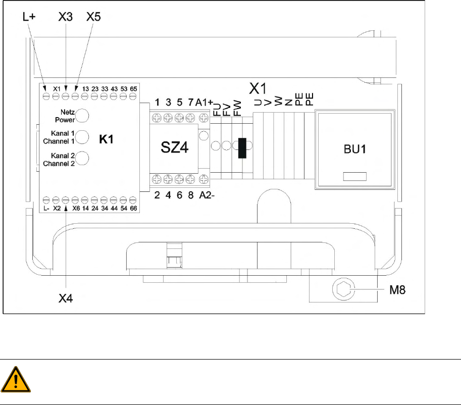
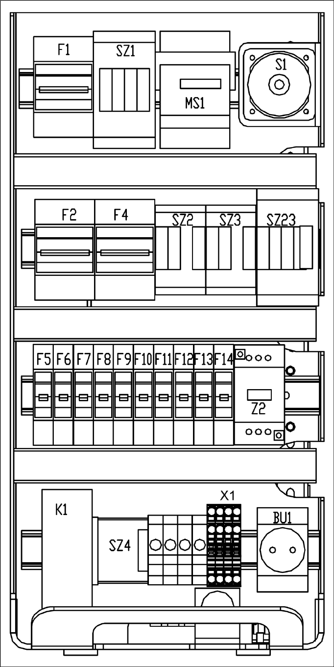
4.1.2.1 Front View
4-2: Power supply unit - front panel - parts overview