00195166-0402_SM_D4_EN.pdf - 第64页
Service Work Gantry Replacing the Y-Axis Sca le 64 Serv ice Manual SIPLACE D4 4.2.4 Replacing the Y - Axis Scale 4.2.5 Replacing the T ensioni ng Keys [00329478-01, 00329485-01] 4.2.5.1 T ools and Equipment Set of DIN …
Service Work
Replacing the X Axis Scale [00329316-01] Gantry
Service Manual SIPLACE D4
63
4.2.2.3 Removing the elastomeric spring
X Switch the machine off and secure it to prevent unauthorized reactivation as described in section
(4.2.1 Preparations for Service Work
J
62 ) .
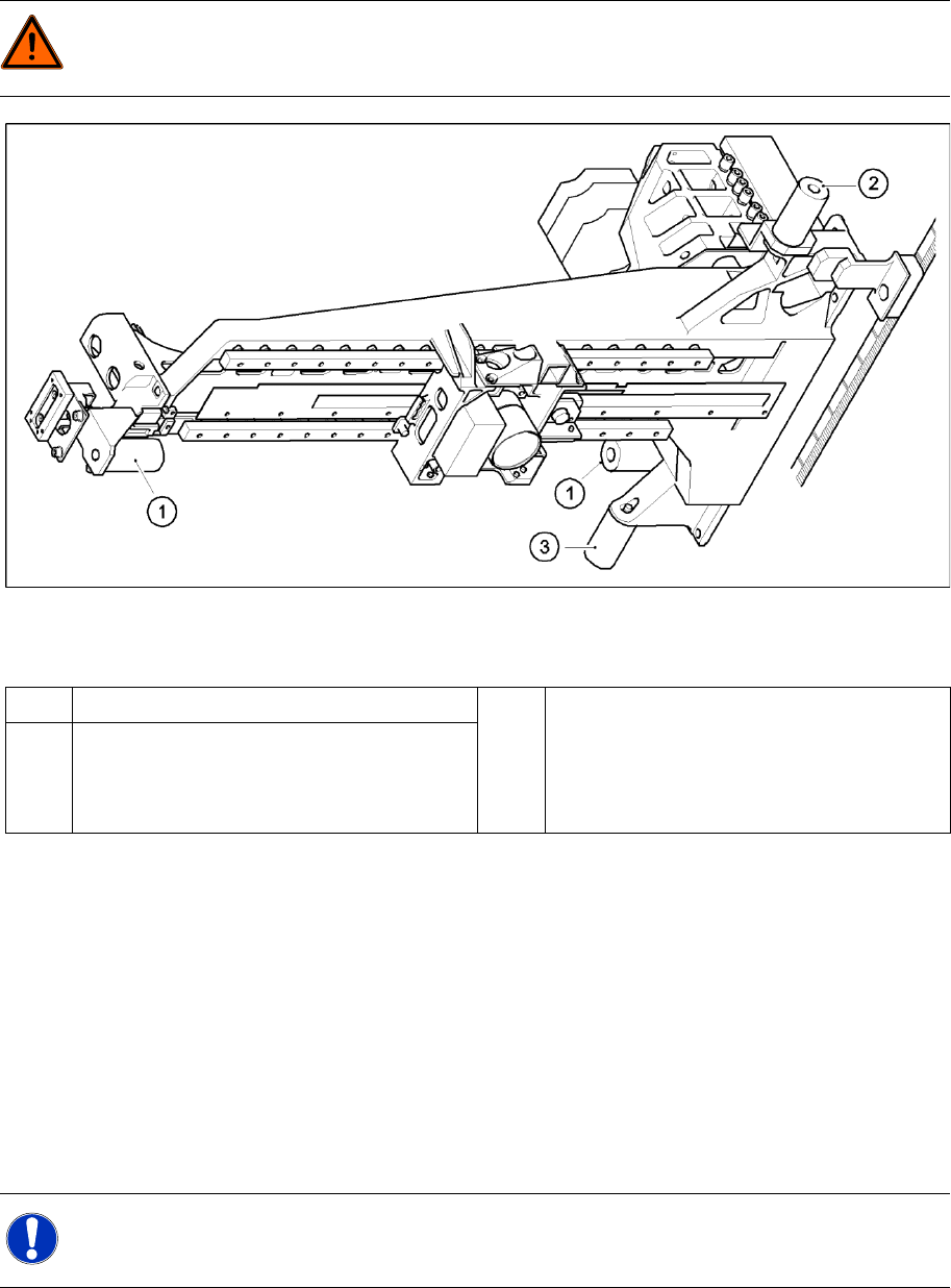
4-11: Replacing the elastomeric spring
Legend
X Loosen the M8x20 hexagon socket-head screw in the drilling in the elastomeric spring.
See also:
J
2.1.2 Safety Instructions for Working with Strong Magnetic Fields [
J
14]
4.2.2.4 Installing the elastomeric spring
X Use the M8 x 20 hexagon socket-head screw to fix the elastomeric spring.
4.2.2.5 Settings
None
4.2.3 Replacing the X Axis Scale [00329316-01]
DANGER: POWERFUL MAGNETIC FIELD
X Always follow the special safety instructions when working in the vicinity of powerful magnetic
fields (see section).
1 Elastomeric spring for X-axis 3 All gantries: elastomeric spring for Y-axis
2 Gantries 1 and 3: elastomeric spring for the Y-
axis
Gantries 2 and 4: bracket instead of elastomeric
spring
NOTE:
This service task may only be performed by specially trained 6,3/$&(service technicians
The procedure is described in a separate manual.

Service Work
Gantry Replacing the Y-Axis Scale
64 Service Manual SIPLACE D4
4.2.4 Replacing the Y-Axis Scale
4.2.5 Replacing the Tensioning Keys [00329478-01, 00329485-01]
4.2.5.1 Tools and Equipment
Set of DIN 911 Allen keys
Belt tension measuring device TSM [00326015-01]
"Measuring belt tensions" operating instructions
4.2.5.2 Parts
Tensioning key [00329478-01]
Tensioning key [00329485-01]
4.2.5.3 Removing the tensioning keys
X Switch the machine off and secure it to prevent unauthorized reactivation as described in section
(4.2.1 Preparations for Service Work
J
62 ) .
X Push the head mount in the direction of the deflection pulley (6).
X To relax the toothed belt (5), proceed as follows:
Loosen the locknut (11),
Turn the hexagon socket-head screw (3) counterclockwise.
Removing the tensioning key, item 1 (synchronizing disk, short)
X Loosen the M4 x 5 hexagon socket-head screw (8).
X Lift out the tensioning key.
Removing the tensioning key, item 2 (synchronizing disk, long)
X Rotate the hexagon socket-head screw (3) out of the spacer bolt (7).
X Lift out the tensioning key.
NOTE:
This service task may only be performed by specially trained 6,3/$&(service technicians
The procedure is described in a separate manual.
Service Work
Replacing the Tensioning Keys [00329478-01, 00329485-01] Gantry
Service Manual SIPLACE D4
65
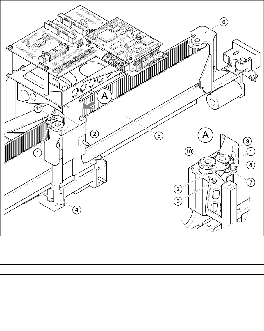
4-12: Replacing the tensioning keys
Legend
1 Tensioning key [00329478-01] 7 Spacer bolt with Benzing U-clip
2 Tensioning key [00329485-01] 8 M4 x 5 hexagon socket-head screw
3 M4 x 35 hexagon socket-head screw for
tensioning the toothed belt
9 Synchronizing disk, short
4 Head mount 10 Synchronizing disk, long
5 Toothed belt for the X-axis 11 Locknut
6 Deflection pulley