00195166-0402_SM_D4_EN.pdf - 第83页
Service W ork Changeover Table Component Handling Service Manual SIPLACE D4 83 4.3.1.6 Final S teps X Check the contact surface for the fe eder modules on the chan geover table: If necessary, clean the surface, as descri…
Service Work
Component Handling Changeover Table
82 Service Manual SIPLACE D4
4.3.1.5 Replacing the Changeover Table Connection Cable
Power supply cable "changeover table"
X Perform the "Preparatory Steps". (See section (4.3.1.2 Preparations for Service Work
J
79 ) .)
You do not need to dismantle the feeder modules.
X Unplug plugs X13 and X15 of the communication unit cable.
X Disconnect the pneumatic hose.
X Disconnect the ground cable at the connection provided.
X The ground cable is looped through the changeover table and fastened at several connections.
To avoid weaving out the complete ground cable, disconnect the cable at the cable shoe.
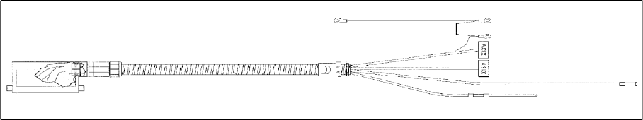
X Open the cord grip and remove the entire cable.
4-28: Cable for changeover table (D4 shown as example)
X Feed the new cable into the cord grip from the top to the bottom.
X Plug in the communication unit connection cable and reconnect the pneumatic system.
X Run the cable and attach cable ties.
X If you have no further parts to be exchanged, perform the appropriate "Final Steps", including a table
function check with SITEST.
See also:
J
4.3.1.6 Final Steps [
J
83]

Service Work
Changeover Table Component Handling
Service Manual SIPLACE D4
83
4.3.1.6 Final Steps
X Check the contact surface for the feeder modules on the changeover table:
If necessary, clean the surface, as described in the User Manual in chapter "Maintenance".
X Place the feeder modules incl. the tape reels in the right order on the changeover table (in
accordance with the specifications for setup optimization).
If an external setup location is available, perform the setup there, incl. inserting the tapes and
checking the allocations „Feeder module / track“ and „Component/ track“.
X Connect all feeder modules to the relevant jack of the communications unit (changeover table
termination panel).
X Switch the machine on. The compressed air is attached. Move the changeover table back into the
machine and connect it. To do this, plug in the changeover table and lower it onto the changeover
table rest and centering point.
Perform the steps in the correct order!
X Make sure that the changeover table has been correctly inserted into the machine!
X Reconnect to the power supply supply.
X If this has not been done yet, insert the tapes now and check the allocation of feeder module and
component (component bar code scanner).
X Step / transport the first component into the pickup position. VISUALLY CHECK the front of the
module to see if all tapes move smoothly into the empty-tape duct.
X After exchanging the cable for the changeover table and/or the communications unit:
Note the DANGER text regarding the SITEST program.
Load the SITEST program and check the changeover table functions.
X Exit the SITEST program.
X Start the placement process.
DANGER: Guard (dummy module)
The changeover table, which has been moved into the machine, must always be completely
equipped with feeder modules or dummy modules (see User Manual and Service Manual,
chapters " "Operational Safety").
DANGER:
The SITEST program may only be started by personnel who have been trained in its use by
$S0$6 and are therefore authorized to do so.
X The cutter must also be completely assembled for work with the SITEST program. The
changeover table must be moved into the machine and docked correctly.
X The changeover table, which has been moved into the machine, must always be completely
equipped with feeder modules or dummy modules (see User Manual and Service Manual,
chapters " "Operational Safety").
X The key switch remains locked (= normal mode = position "0").
Service Work
Component Handling Cutter
84 Service Manual SIPLACE D4
4.3.2 Cutter
See also:
J
2.1.4 Safety Instructions for Work on the Cutting Device [
J
15]
4.3.2.1 Safety Instructions
4.3.2.2 Parts
All spare parts, plus the corresponding diagrams and article numbers, can be found in the D4 spare parts
catalogue.
See also:
J
4.3.2.4 Overview of Cutter [
J
86]
DANGER:
The safety instructions in the chapter "Operational Safety" in the operating manual and this
service manual take priority.
The machine is supplied with
219/380 V +/- 5% or
230/400 V +/- 5% or
239/415 V +/- 5% or
117/204 V +/- 5% or
133/230 V +/- 5%,
50/60 Hz mains voltage.
Inside the machine base this is true even while the master switch is turned off.
X The machine has to be switched OFF and disconnected from the line before you perform any
work in the area of the cutter.
X In addition, the compressed air supply must be turned off at the main valve of the compressed
air unit in the machine base and the compressed air lines must be bled by actuating the
needle valve on the compressed air unit.
X Always secure the machine against unauthorized reactivation, as described in the User
Manual, chapter "Lock-Out and Tag-Out Procedure ...".
WARNING:
X Wear appropriately thick protective gloves when working near the blades/the tape deflector!
X There is a high risk of injury from stationary blades and moveable blades and from the tape
deflector of the cutter, even when the machine has been turned off!
X Never reach into the pneumatic cutter from below or into the empty-tape duct from above, not
even to resolve a problem (e.g. when tape is jammed).
NOTE:
This manual applies for the pneumatic cutter version 04 and the corresponding empty tape duct
version 03.
Version 04 of the cutter contains, for example, a tape deflector for the tapes, which is fitted
above the moveable blades.