00195166-0402_SM_D4_EN.pdf - 第85页
Service W ork Cutter Component Handling Service Manual SIPLACE D4 85 4.3.2.3 T ools, Expendable Materials, Document ation Thick protective gloves Set of socket wrenches, cro ss-slotted screwdr iver size 4 Open-end …

Service Work
Component Handling Cutter
84 Service Manual SIPLACE D4
4.3.2 Cutter
See also:
J
2.1.4 Safety Instructions for Work on the Cutting Device [
J
15]
4.3.2.1 Safety Instructions
4.3.2.2 Parts
All spare parts, plus the corresponding diagrams and article numbers, can be found in the D4 spare parts
catalogue.
See also:
J
4.3.2.4 Overview of Cutter [
J
86]
DANGER:
The safety instructions in the chapter "Operational Safety" in the operating manual and this
service manual take priority.
The machine is supplied with
219/380 V +/- 5% or
230/400 V +/- 5% or
239/415 V +/- 5% or
117/204 V +/- 5% or
133/230 V +/- 5%,
50/60 Hz mains voltage.
Inside the machine base this is true even while the master switch is turned off.
X The machine has to be switched OFF and disconnected from the line before you perform any
work in the area of the cutter.
X In addition, the compressed air supply must be turned off at the main valve of the compressed
air unit in the machine base and the compressed air lines must be bled by actuating the
needle valve on the compressed air unit.
X Always secure the machine against unauthorized reactivation, as described in the User
Manual, chapter "Lock-Out and Tag-Out Procedure ...".
WARNING:
X Wear appropriately thick protective gloves when working near the blades/the tape deflector!
X There is a high risk of injury from stationary blades and moveable blades and from the tape
deflector of the cutter, even when the machine has been turned off!
X Never reach into the pneumatic cutter from below or into the empty-tape duct from above, not
even to resolve a problem (e.g. when tape is jammed).
NOTE:
This manual applies for the pneumatic cutter version 04 and the corresponding empty tape duct
version 03.
Version 04 of the cutter contains, for example, a tape deflector for the tapes, which is fitted
above the moveable blades.
Service Work
Cutter Component Handling
Service Manual SIPLACE D4
85
4.3.2.3 Tools, Expendable Materials, Documentation
Thick protective gloves
Set of socket wrenches, cross-slotted screwdriver size 4
Open-end wrench, width across flats 10; 1
Torque wrench, Diagonal cutter, Sliding caliper
Feeler gauge: 0.05mm; 1.0mm; 1.5mm; 2.0mm; 2.50 mm
Straight-edge (for check of tape deflector)
Mounting plate [00312731-01]
2 large parallel clamps (or mounting plate, see above)
Flat, sturdy work bench to fasten the removed cutter (or mounting plate, see above)
Loctite No. 234 [00334892-01]
Molykote paste 250 g [02100335-01] (recommended) or ISOFLEX TOPAS NCA 52 tube 50g
[00330850-01]
Water-insoluble, fine-tip marker and
a dry and clean cloth
Current SIPLACE D4 spare parts catalogue and SIPLACE D4 circuit diagrams
SITEST program and current SITEST operating manual
See also:
J
5 Measuring Equipment and Tools [
J
201]
Service Work
Component Handling Cutter
86 Service Manual SIPLACE D4
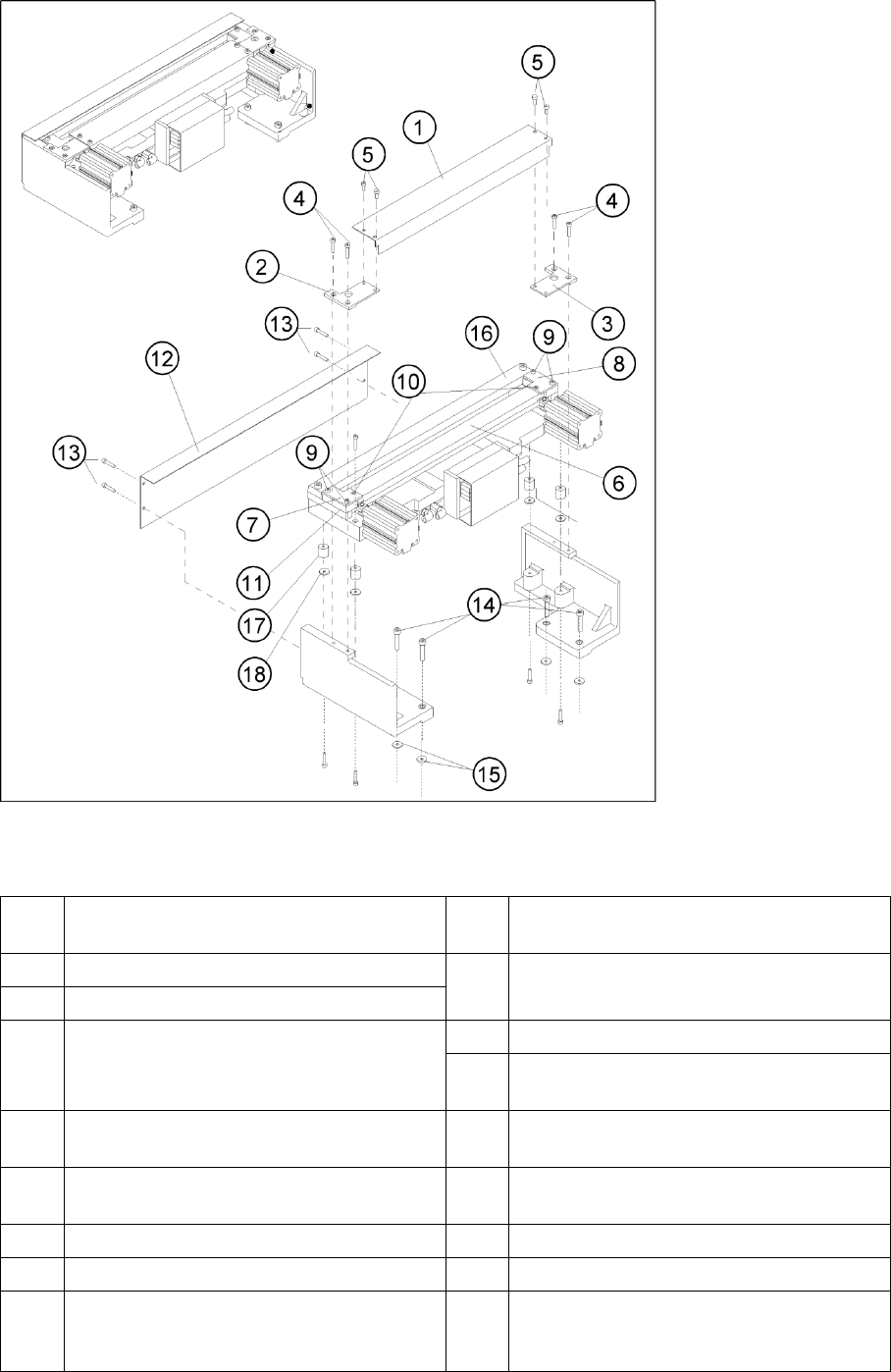
4.3.2.4 Overview of Cutter
4-29: Overview: Removing and Installing the Cover Plate and the Tape Deflector
Legend
1 Cover plate 10 Screws to fasten the tape deflector: 1
countersunk screw each -> do not loosen!
2 Cover plate holder, left 11 Holddowns (at left and right) with spacers
inserted underneath them
3 Cover plate holder, right
4 Screws to fasten the cover plate holder:
2 hexagon socket head screws M4 x 8 DIN 84
or 2 countersunk screws R M4 x 6 DIN 965 each
12 Deflector plate
13 Screws to fasten the deflector plate: 4 socket
hex head cap screws M4 x 8
5 Screws to fasten the cover plate (incl. tape
deflector) -> do not loosen!
14 Screws to fasten the cutter on the machine base
4 socket hex head cap screws M 6 x 25 *)
6 Tape deflector (with moveable blade
underneath)
15 Any disks or plates installed underneath
7 Tape deflector holder, left 16 Stationary blade
8 Tape deflector holder, right 17 Rubber-metal vibration damper
9 Screws to fasten the tape deflector holders: 2
socket hex head cap screws M4 x 35 each on
the left and right
18 Any disks and spring washers installed
underneath