00195166-0402_SM_D4_EN.pdf - 第86页
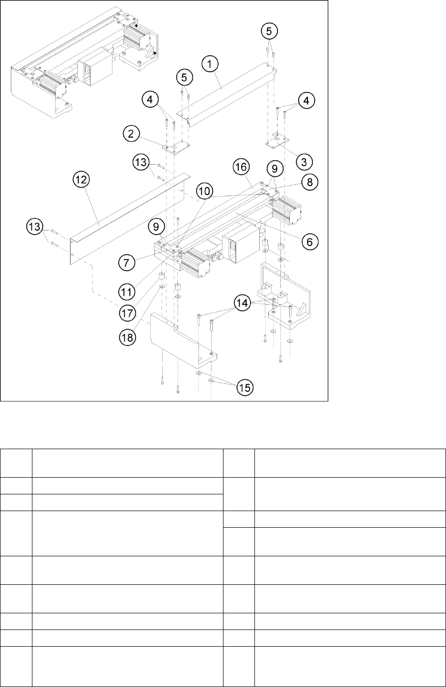
Service Work Component Handling Cutter 86 Serv ice Manual SIPLACE D4 4.3.2.4 Overview of Cutter 4-29: Overview: Removing and Installing the Cover Plate and the Tape Deflector Legend 1 Cover plate 10 Screws to fa sten the…
Service Work
Cutter Component Handling
Service Manual SIPLACE D4
85
4.3.2.3 Tools, Expendable Materials, Documentation
Thick protective gloves
Set of socket wrenches, cross-slotted screwdriver size 4
Open-end wrench, width across flats 10; 1
Torque wrench, Diagonal cutter, Sliding caliper
Feeler gauge: 0.05mm; 1.0mm; 1.5mm; 2.0mm; 2.50 mm
Straight-edge (for check of tape deflector)
Mounting plate [00312731-01]
2 large parallel clamps (or mounting plate, see above)
Flat, sturdy work bench to fasten the removed cutter (or mounting plate, see above)
Loctite No. 234 [00334892-01]
Molykote paste 250 g [02100335-01] (recommended) or ISOFLEX TOPAS NCA 52 tube 50g
[00330850-01]
Water-insoluble, fine-tip marker and
a dry and clean cloth
Current SIPLACE D4 spare parts catalogue and SIPLACE D4 circuit diagrams
SITEST program and current SITEST operating manual
See also:
J
5 Measuring Equipment and Tools [
J
201]
Service Work
Component Handling Cutter
86 Service Manual SIPLACE D4
4.3.2.4 Overview of Cutter
4-29: Overview: Removing and Installing the Cover Plate and the Tape Deflector
Legend
1 Cover plate 10 Screws to fasten the tape deflector: 1
countersunk screw each -> do not loosen!
2 Cover plate holder, left 11 Holddowns (at left and right) with spacers
inserted underneath them
3 Cover plate holder, right
4 Screws to fasten the cover plate holder:
2 hexagon socket head screws M4 x 8 DIN 84
or 2 countersunk screws R M4 x 6 DIN 965 each
12 Deflector plate
13 Screws to fasten the deflector plate: 4 socket
hex head cap screws M4 x 8
5 Screws to fasten the cover plate (incl. tape
deflector) -> do not loosen!
14 Screws to fasten the cutter on the machine base
4 socket hex head cap screws M 6 x 25 *)
6 Tape deflector (with moveable blade
underneath)
15 Any disks or plates installed underneath
7 Tape deflector holder, left 16 Stationary blade
8 Tape deflector holder, right 17 Rubber-metal vibration damper
9 Screws to fasten the tape deflector holders: 2
socket hex head cap screws M4 x 35 each on
the left and right
18 Any disks and spring washers installed
underneath

Service Work
Cutter Component Handling
Service Manual SIPLACE D4
87
*) Loosen these screws only when removing/installing the cutter.
See also:
J
6.4.3 Check the gap between the empty-tape baffle, inside and the leading edge of the tape deflector.
[
J
241]
J
4.3.2.14 Final Steps [
J
114]
Tightening Torques for Cutter Screws
4.3.2.5 Exchanging the Pneumatic Cutter
CAUTION: Tighten the screws to the correct torque.
Thread Tightening torque (Nm)
M3 1.0 – 1.3
M4 2.7 – 3.0
M5 5.5 – 6.0
M6 9.5 – 10.2
WARNING:
X Wear thick protective gloves
X When removing the cutter, hold it only on the left and right, on the outside.
X Never support the cutter on your body (e.g. on your knee or thighs). Do not place your feet
under the cutter.
X You could injury yourself severely or at least damage your clothing.
X Make certain that no one can injury themselves on the cutter, after it has been dismantled.