00195166-0402_SM_D4_EN.pdf - 第87页
Service W ork Cutter Component Handling Service Manual SIPLACE D4 87 *) Loosen these screws only when removing/installing the cutter. See also: J 6.4.3 Check the gap between th e empty-tape baffle, inside an d the leadin…
Service Work
Component Handling Cutter
86 Service Manual SIPLACE D4
4.3.2.4 Overview of Cutter
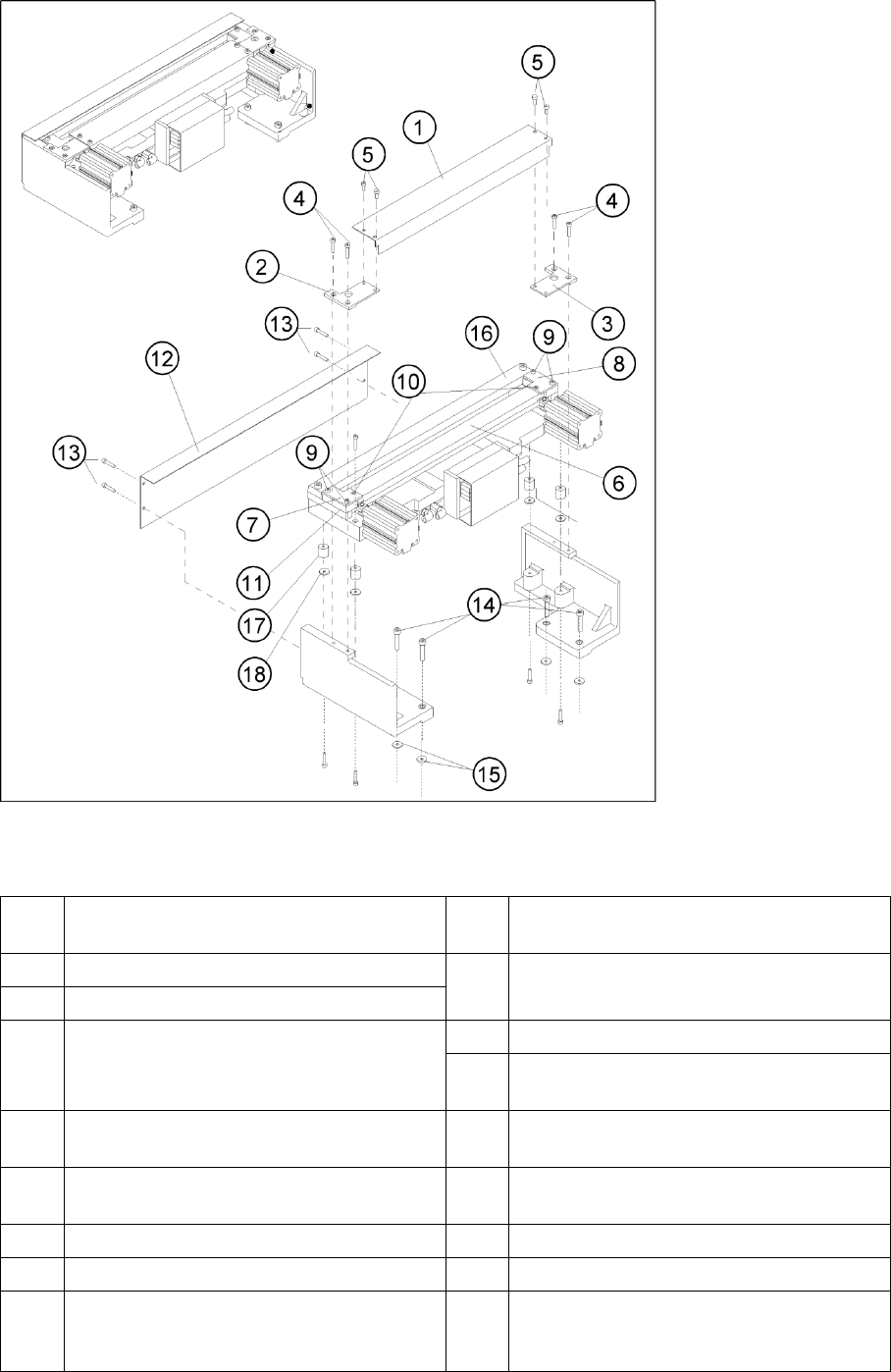
4-29: Overview: Removing and Installing the Cover Plate and the Tape Deflector
Legend
1 Cover plate 10 Screws to fasten the tape deflector: 1
countersunk screw each -> do not loosen!
2 Cover plate holder, left 11 Holddowns (at left and right) with spacers
inserted underneath them
3 Cover plate holder, right
4 Screws to fasten the cover plate holder:
2 hexagon socket head screws M4 x 8 DIN 84
or 2 countersunk screws R M4 x 6 DIN 965 each
12 Deflector plate
13 Screws to fasten the deflector plate: 4 socket
hex head cap screws M4 x 8
5 Screws to fasten the cover plate (incl. tape
deflector) -> do not loosen!
14 Screws to fasten the cutter on the machine base
4 socket hex head cap screws M 6 x 25 *)
6 Tape deflector (with moveable blade
underneath)
15 Any disks or plates installed underneath
7 Tape deflector holder, left 16 Stationary blade
8 Tape deflector holder, right 17 Rubber-metal vibration damper
9 Screws to fasten the tape deflector holders: 2
socket hex head cap screws M4 x 35 each on
the left and right
18 Any disks and spring washers installed
underneath
Service Work
Cutter Component Handling
Service Manual SIPLACE D4
87
*) Loosen these screws only when removing/installing the cutter.
See also:
J
6.4.3 Check the gap between the empty-tape baffle, inside and the leading edge of the tape deflector.
[
J
241]
J
4.3.2.14 Final Steps [
J
114]
Tightening Torques for Cutter Screws
4.3.2.5 Exchanging the Pneumatic Cutter
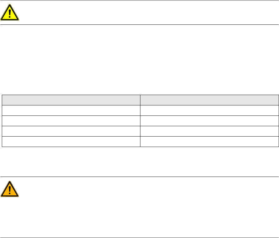
CAUTION: Tighten the screws to the correct torque.
Thread Tightening torque (Nm)
M3 1.0 – 1.3
M4 2.7 – 3.0
M5 5.5 – 6.0
M6 9.5 – 10.2
WARNING:
X Wear thick protective gloves
X When removing the cutter, hold it only on the left and right, on the outside.
X Never support the cutter on your body (e.g. on your knee or thighs). Do not place your feet
under the cutter.
X You could injury yourself severely or at least damage your clothing.
X Make certain that no one can injury themselves on the cutter, after it has been dismantled.
Service Work
Component Handling Cutter
88 Service Manual SIPLACE D4
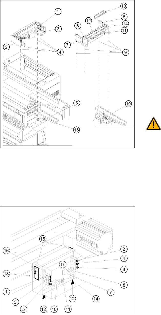
Removing the Cutter
X Turn the machine and then the flow of
compressed air ON.
X Disconnect the movable changeover table
from the machine and move it out of the
machine.
X Switch off the supply of compressed air at the
compressed air unit and actuate the needle
valve on the compressed air unit to bleed the
compressed air lines.
X Turn the machine OFF, disconnect the
machine from the line and turn off the flow of
compressed air at the compressed air unit.
X Loosen the screws fastening the empty-tape
duct assembly (6) (M6x35), lift the empty-tape
duct and place it carefully down on the PCB
conveyor. The nozzle changer remains fixed
to the empty-tape duct.
WARNING:
There is always a risk of injuring
yourself on the cutting edge of the
blades.
X For this reason, the deflector plate,
the cover and the protective sheet
must be left in place.
X Undo the fixtures for the stop buffer assembly
(15) (two hexagon-socket head screws M8x25
on each side) on the left and right-hand sides
of the machine base, under the surface
supporting the changeover table.
X Remove the cover from the control board (14).
X Unplug the press-fit connection of the power
supply and the drive from the control board
(11, 10).