00196428-0102_AI_Reconfig_Kit_X-Serie_CPP_DE EN - 第103页
Head Reconfiguration Kit 2 Assembly Instructions Head Reconfiguration Kit CPP fo r the SIPLACE X Ser ies Issue 03/2010 2.7 Installing the CPP Placement H ead 103 X If the distance is too large, insert shim plates: Shim p…
2 Assembly Instructions Head Reconfiguration Kit CPP for the SIPLACE X Series Head Reconfiguration Kit
2.7 Installing the CPP Placement Head Issue 03/2010
102
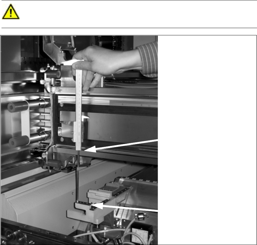
X Push the placement head outwards for the measurement.
X Place the caliper on the top edge of the nozzle reject device and measure the distance to the
top edge of the bottom linear guide rail of the X axis.
2
2
X Set the distance to 139.0 ±0.2 mm for all placement heads.
When the distance is correct, continue with installing the nozzle changer into the placement
machine.
CAUTION:
Hold the caliper vertically! 2
Rest the bottom edge of the cali-
per on the reject device .
Rest the top edge of the caliper on
the linear guide rail.
Head Reconfiguration Kit 2 Assembly Instructions Head Reconfiguration Kit CPP for the SIPLACE X Series
Issue 03/2010 2.7 Installing the CPP Placement Head
103
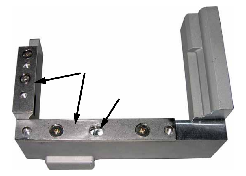
X If the distance is too large, insert shim plates:
Shim plate for nozzle reject device [03039514-xx and 03021079-xx],
screws DIN7991 M4x20 - 8.8 [00333782-xx].
2
X Remove the cover plate above the component reject bin.
Slot
Shim plates
2 Assembly Instructions Head Reconfiguration Kit CPP for the SIPLACE X Series Head Reconfiguration Kit
2.7 Installing the CPP Placement Head Issue 03/2010
104
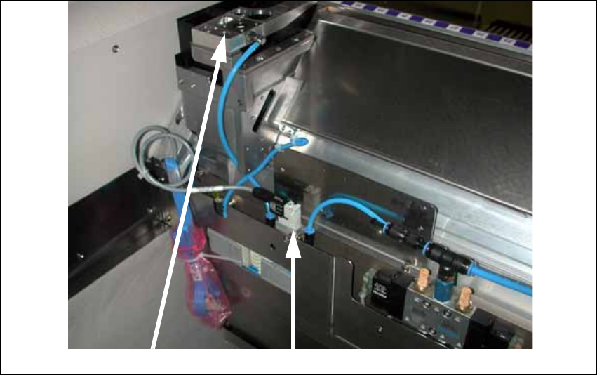
X Install the valve for nozzle station cplt. [03055785-xx] at the component trolley docking unit,
using the two DIN912-M3 x 16-A2-70 screws.
X Replace the plug QSC-H at the solenoid valve of the docking unit control by the "Y press-fit
connection with push-on socket QSY-6H-4" [03055792-xx].
X Connect the hose "PUN4 125 mm" with the Y press-fit connection with push-on socket and
the "valve for nozzle station cplt." [03055785-xx].
The second hole on the Y press-fit connection must be connected to the pneumatic hose of
the nozzle changer or closed with the plug QSC-4H.
X Connect the hose "PUN4 200 mm" to the "valve for nozzle station cplt." and the nozzle station.
X Connect the "Cable dock.unit X-series: nozzle station" [03053223-xx] that is already prewired
in the component trolley docking unit with the "valve for nozzle station cplt."
X Fix the "valve for nozzle station cplt." to the component trolley docking unit as shown in the
figure above, using two "DIN 7991-M4 x 20-8.8" [00333782-xx] / "DIN 912-M3 x 16-A2-70"
[00325349-xx] screws .
Insert the reject bin [03048638-xx] and the component reject bin up to 6x6 [03049954-xx]. On
older machines use version [03039042-xx ] instead of [03049954-xx]. The reject bin must not be
higher than the conveyor side in any case. 2
If the reject bin sensor is already installed, it must be repositioned for this reject bin. Use the sen-
sor mounting [03077835-xx] for this. See the Assembly Instructions Reject Bin Sensor SIPLACE
/ X-Series / D3 [00194716-xx] for more details. 2
Nozzle station Valve