00196428-0102_AI_Reconfig_Kit_X-Serie_CPP_DE EN - 第108页
2 Assembly Instructions Head Reconfiguration Kit CPP for the SIPLACE X Series Head Reconfiguration Kit 2.7 Installing the CPP Placement Head Issue 03/2010 108 X Mark the ad justed potentiom eters (A) and (D) with gray sc…
Head Reconfiguration Kit 2 Assembly Instructions Head Reconfiguration Kit CPP for the SIPLACE X Series
Issue 03/2010 2.7 Installing the CPP Placement Head
107
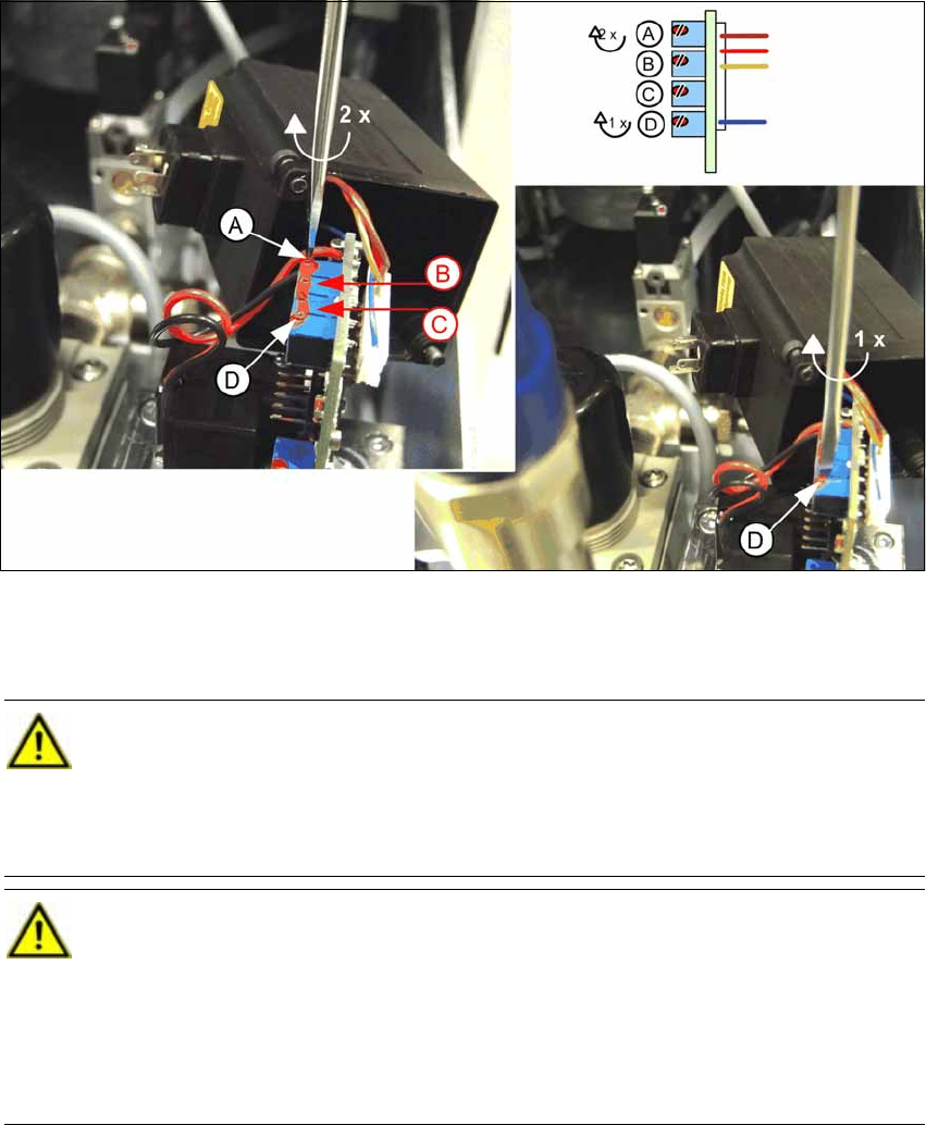
X Adjust the potentiometer (A) by 2 turns clockwise and potentiometer (D) by one turn clockwise.
Use a size 0 screwdriver to do this. The two middle potentiometers (B) and (C) must not be
adjusted under any circumstances..
CAUTION:
The potentiometers are endless rotation potentiometers, i.e. they have no end position.
If the potentiometers are set incorrectly, this setting cannot be restored in the factory.
This can result in sporadic deactivation of the compressed air. In this event, it is only pos-
sible to replace the pneumatic valve by a new one. [03038725-03] 2
CAUTION:
As of FS 03, the correct setting is guaranteed by the manufacturer (expected as of April
2010). This setting is suitable for all head configurations and must not be changed again. 2
At the same time, the pressure valves will be labeled with the SIPLACE item number
clearly indicating FS03. 2
Pressure valves earlier than FS 03 do not bear a label with a SIPLACE item number. 2
2 Assembly Instructions Head Reconfiguration Kit CPP for the SIPLACE X Series Head Reconfiguration Kit
2.7 Installing the CPP Placement Head Issue 03/2010
108
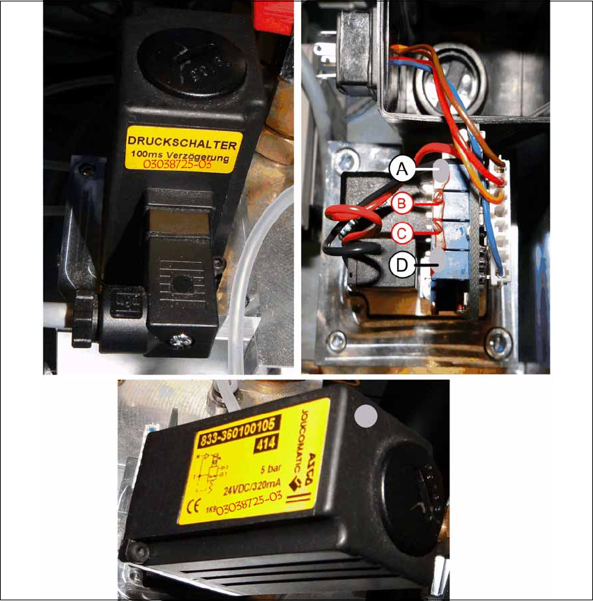
X Mark the adjusted potentiometers (A) and (D) with gray screw locking varnish [00318199-xx].
X Screw the cover back on to the valve and plug in the connector again.
X Also mark the pressure regulation valve with gray screw locking varnish and write the item
number and the new FS 03038725-03 on the existing label.
X Carefully push the pneumatic module back into the machine and secure it with the screw.
X Reconnect the compressed air supply and close the cover over the pneumatic supply.

Head Reconfiguration Kit 2 Assembly Instructions Head Reconfiguration Kit CPP for the SIPLACE X Series
Issue 03/2010 2.7 Installing the CPP Placement Head
109
2.7.8 Installing the Nozzle Changer Option
X For installing the nozzle changer, refer to the Assembly Instructions for Nozzle Changer X-Se-
ries [00194482-xx].
2.7.9 Installing the Reject Bin Sensor Option
2.7.10 Installing the Stationary Camera Option
CAUTION: Danger of crashing
Always operate the placement heads with the appropriate nozzle changer for the rele-
vant head. There is a danger of crashing when a false nozzle changer is used! 2
NOTE:
The nozzle changer of the CPP head can only be operated on machines with CAN
nodes. 2
NOTE:
When using the reject bin sensor option, an additional sensor for the large component
reject bin must be installed [03079030-xx]. 2
For details on the reject bin sensor option, refer to the Assembly Instructions "Reject Bin
Sensor SIPLACE / X-Series / D3" [00194716-xx]. 2
NOTE:
For details on the stationary camera, refer to the Assembly Instructions "Stationary Cam-
era SIPLACE X-Series" [00194554-03]. 2
The CPP head can only be used with stationary cameras of version -04 or higher. 2
NOTE:
Two "DIN 913 - M 6 x 50-ST" [03005958-xx] screws for securing the mark caul before
removing the camera are included in the parts set. 2