00196428-0102_AI_Reconfig_Kit_X-Serie_CPP_DE EN - 第109页
Head Reconfiguration Kit 2 Assembly Instructions Head Reconfiguration Kit CPP fo r the SIPLACE X Ser ies Issue 03/2010 2.7 Installing the CPP Placement H ead 109 2.7.8 Inst alling the Nozzle Changer Option X For inst all…
2 Assembly Instructions Head Reconfiguration Kit CPP for the SIPLACE X Series Head Reconfiguration Kit
2.7 Installing the CPP Placement Head Issue 03/2010
108
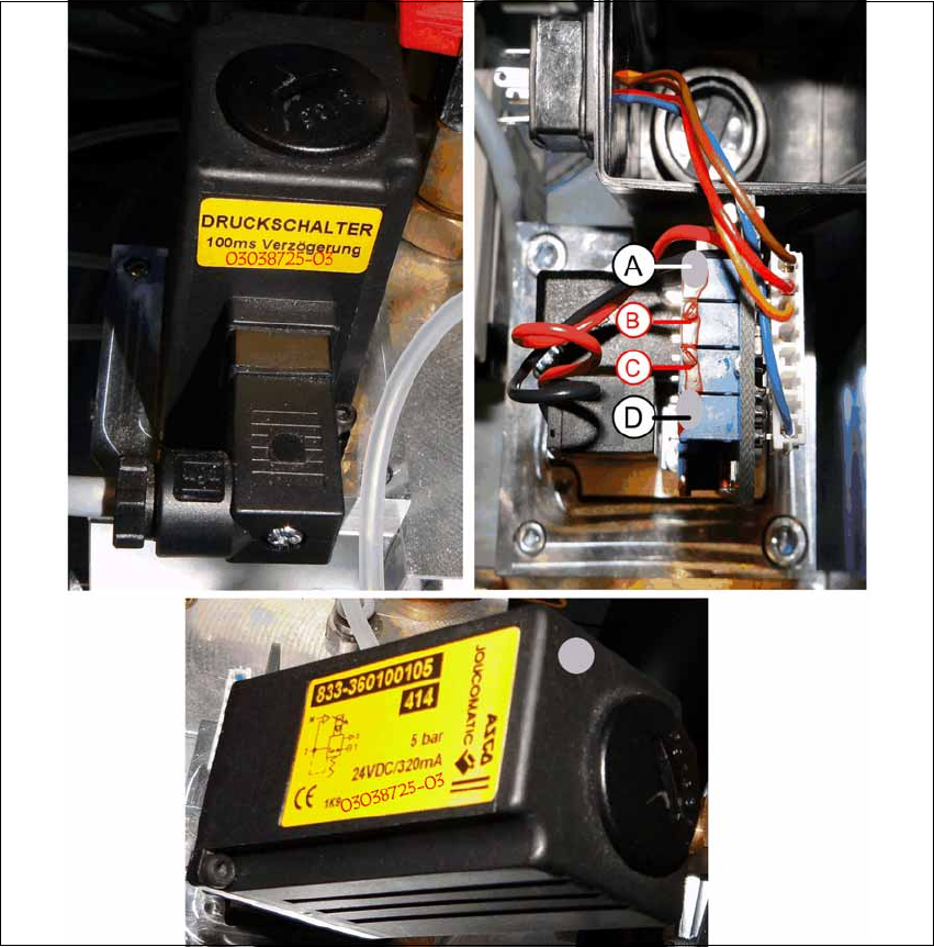
X Mark the adjusted potentiometers (A) and (D) with gray screw locking varnish [00318199-xx].
X Screw the cover back on to the valve and plug in the connector again.
X Also mark the pressure regulation valve with gray screw locking varnish and write the item
number and the new FS 03038725-03 on the existing label.
X Carefully push the pneumatic module back into the machine and secure it with the screw.
X Reconnect the compressed air supply and close the cover over the pneumatic supply.

Head Reconfiguration Kit 2 Assembly Instructions Head Reconfiguration Kit CPP for the SIPLACE X Series
Issue 03/2010 2.7 Installing the CPP Placement Head
109
2.7.8 Installing the Nozzle Changer Option
X For installing the nozzle changer, refer to the Assembly Instructions for Nozzle Changer X-Se-
ries [00194482-xx].
2.7.9 Installing the Reject Bin Sensor Option
2.7.10 Installing the Stationary Camera Option
CAUTION: Danger of crashing
Always operate the placement heads with the appropriate nozzle changer for the rele-
vant head. There is a danger of crashing when a false nozzle changer is used! 2
NOTE:
The nozzle changer of the CPP head can only be operated on machines with CAN
nodes. 2
NOTE:
When using the reject bin sensor option, an additional sensor for the large component
reject bin must be installed [03079030-xx]. 2
For details on the reject bin sensor option, refer to the Assembly Instructions "Reject Bin
Sensor SIPLACE / X-Series / D3" [00194716-xx]. 2
NOTE:
For details on the stationary camera, refer to the Assembly Instructions "Stationary Cam-
era SIPLACE X-Series" [00194554-03]. 2
The CPP head can only be used with stationary cameras of version -04 or higher. 2
NOTE:
Two "DIN 913 - M 6 x 50-ST" [03005958-xx] screws for securing the mark caul before
removing the camera are included in the parts set. 2
2 Assembly Instructions Head Reconfiguration Kit CPP for the SIPLACE X Series Head Reconfiguration Kit
2.7 Installing the CPP Placement Head Issue 03/2010
110
2.7.11 Connections on the Hotlink Board (Box PC)
2
2
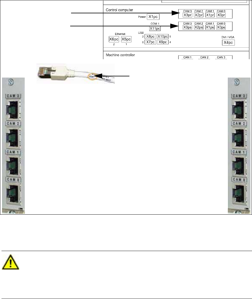
X Connect the hotlink cables for the corresponding component camera.
IC/FC camera in PA 1
X3pr
PCB/component cam-
eras in PA 1, gantry 1,
X0pr
PCB/component cam-
eras in PA 1, gantry 4,
X1ps
IC camera in PA 1
X2ps
IC/FC camera in PA 2
X3pr
IC camera in PA 2
X2ps
PCB/component cameras in
PA 2, gantry 3,
X1ps
PCB/component cameras in
PA 2, gantry 2,
X1ps
Labeling of the hotlink cable
Hotlink board for cam-
eras in PA 1
Hotlink board for cam-
eras in PA 2
CAUTION:
The hotlink cables of the IC and FC cameras must be disconnected for the placement
area where a C&P20 head is used!
Unused hotlink cables must not be connected!
Do not confuse the hotlink cables with twisted pair cables! 2