00196428-0102_AI_Reconfig_Kit_X-Serie_CPP_DE EN - 第114页
2 Assembly Instructions Head Reconfiguration Kit CPP for the SIPLACE X Series Head Reconfiguration Kit 2.8 Removing the Placement Head Issue 03/2010 114 2.8.2 Saving the Existing Machine Dat a X Plug a USB stick or an ot…
Head Reconfiguration Kit 2 Assembly Instructions Head Reconfiguration Kit CPP for the SIPLACE X Series
Issue 03/2010 2.8 Removing the Placement Head
113
2.8 Removing the Placement Head
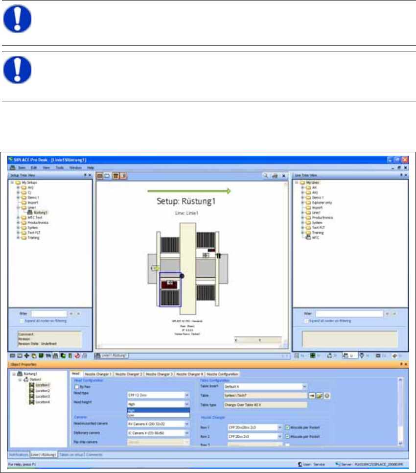
2.8.1 Configuration of the Placement Heads with SIPLACE Pro
X In SIPLACE Pro stop all jobs of the line.
X In the "Properties Setup" dialog enter the new placement head type, the camera type and the
nozzle changer configuration of the corresponding machine location.
2
X Perform a new optimization of the setup in SILPACE Pro. In doing so, make sure to set the
correct head height.
NOTE:
Make a backup of the SIPLACE Pro data. 2
NOTE:
It is recommended to enter the new head into the setup at this point in time (cameras
and nozzles) and to perform an optimization for the setups. 2
2 Assembly Instructions Head Reconfiguration Kit CPP for the SIPLACE X Series Head Reconfiguration Kit
2.8 Removing the Placement Head Issue 03/2010
114
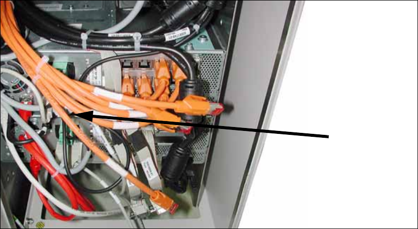
2.8.2 Saving the Existing Machine Data
X Plug a USB stick or another appropriate storage medium into the USB port of the station com-
puter.
2
2
X Save the machine data to the storage medium. To do so, select Service --> machine data ->
save...
X Undock the component trolleys.
X Shutdown the station computer and switch off the placement machine at the main switch. Dis-
connect the machine from the power supply and the pneumatic supply.
USB stick
BoxPC
Head Reconfiguration Kit 2 Assembly Instructions Head Reconfiguration Kit CPP for the SIPLACE X Series
Issue 03/2010 2.8 Removing the Placement Head
115
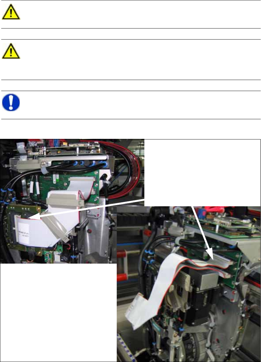
2.8.3 Removing the CPP Placement Head
X Disconnect the two flat ribbon cables.
CAUTION:
Wear an ESD wrist strap during the whole work on the placement head and the servos!2
CAUTION:
Remove the axis and servo cards.
For this purpose, observe the overviews in the annex in Chapter 2.9.1 Configuration Axis
Unit A364. 2
NOTE:
The reconfiguration can most conveniently be performed via locations 2 and 4. 2
Disconnecting the flat ribbon cables