00196428-0102_AI_Reconfig_Kit_X-Serie_CPP_DE EN - 第122页
2 Assembly Instructions Head Reconfiguration Kit CPP for the SIPLACE X Series Head Reconfiguration Kit 2.8 Removing the Placement Head Issue 03/2010 122 2.8.7 Removing the "Nozzle St ation" Option X For remov i…
Head Reconfiguration Kit 2 Assembly Instructions Head Reconfiguration Kit CPP for the SIPLACE X Series
Issue 03/2010 2.8 Removing the Placement Head
121
2.8.6 Removing the Nozzle Station
When switching to a C&P 20 head the "nozzle station CPx cplt." X-Series" [03073328-xx] can be
reused. 2
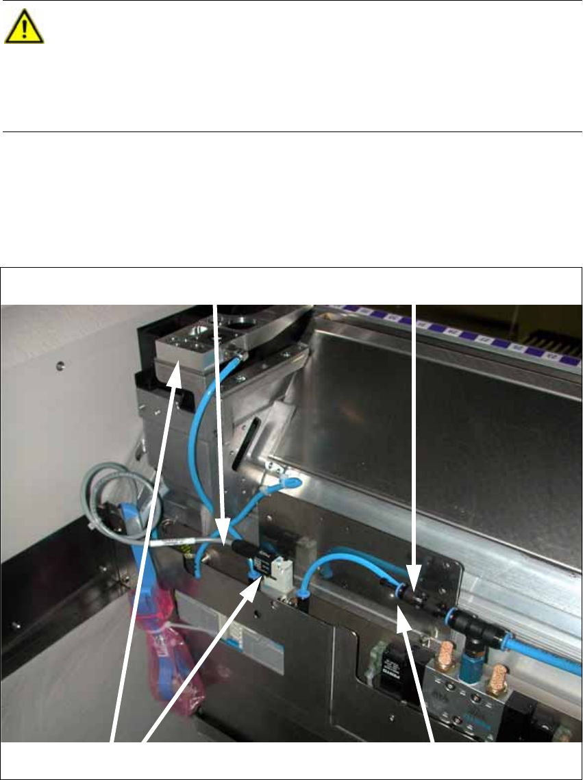
X Disconnect the cable from the solenoid valve (see photo below).
X Disconnect the Y distributor at the solenoid valve of the component trolley docking unit (see
photo below).
X Remove the nozzle station and the solenoid valve (see photo below).
X Close the T piece of the pneumatic supply with a plug QSC-4H [00330249-xx]
CAUTION:
Depending on the installation location (single gantry placement area) the component
trolley docking unit must be released and pushed outwards. To do this, it is absolutely
necessary to read the relevant Service Manual.
When the work is completed refit the component trolley docking unit and calibrate all
add-on parts (nozzle changer). 2
Cable at the solenoid valve
Disconnecting the Y distributor
Removing the nozzle station and the solenoid valve
Closing the T piece
2 Assembly Instructions Head Reconfiguration Kit CPP for the SIPLACE X Series Head Reconfiguration Kit
2.8 Removing the Placement Head Issue 03/2010
122
2.8.7 Removing the "Nozzle Station" Option
X For removing
the nozzle changer, refer to the Assembly Instructions for Nozzle Changer X-Series
[00196432-xx].
2.8.8 Removing the "Reject Bin Sensor" Option
2.8.9 Removing the "Stationary Camera" Option
2.8.10 Removing the "MTC" Option
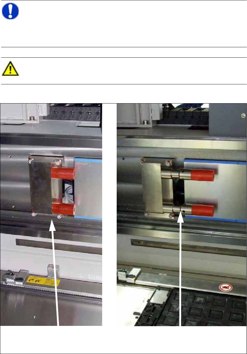
If the CPP is operated with an MTC, the Y stop must be installed on the MTC side with an exten-
sion. 2
With a TwinHead, no extensions are necessary. 2
CAUTION: Danger of crashing
Always operate the placement heads with the appropriate nozzle changer for the rele-
vant head and the correct magazines. There is a danger of crashing when a false nozzle
changer is used.
When switching to a C&P20 head it suffices to change the magazines. 2
NOTE:
The nozzle changer of the CPP head can only be operated on machines with CAN
nodes. 2
NOTE:
When using the reject bin sensor option, an additional sensor for the large component
reject bin must be installed [03079030-xx]. 2
For details on the reject bin sensor option, refer to the Assembly Instructions "Reject Bin
Sensor SIPLACE / X-Series / D3 " [
00194716-xx]. 2
NOTE:
For details on the stationary camera, refer to the Assembly Instructions "Stationary Cam-
era SIPLACE X-Series" [
00194554-03]. 2
Head Reconfiguration Kit 2 Assembly Instructions Head Reconfiguration Kit CPP for the SIPLACE X Series
Issue 03/2010 2.8 Removing the Placement Head
123
X Remove the two extensions for the Y axis stop [03075963-01] "Adaption Stop Y Axis MTC").
NOTE:
For more details on MTC2, refer to the
Assembly Instructions "MTC2 on Component Trolley Docking Unit, X-S" [00194725-xx]
and the Installation Instructions "
MTC2 on SIPLACE HF" [00193897-xx]. 2
CAUTION:
An MTC cannot be used with an C&P20(A). 2
Standard Y axis stop (MTC with Twin-
Head)
Y stop for MTC with CPP