00196428-0102_AI_Reconfig_Kit_X-Serie_CPP_DE EN - 第78页
2 Assembly Instructions Head Reconfiguration Kit CPP for the SIPLACE X Series Head Reconfiguration Kit 2.6 Replacing the Placement Head - Procedure Issue 03/2010 78 2.6.2 Removing the Placement Head - Procedure 2 NOTE: T…
Head Reconfiguration Kit 2 Assembly Instructions Head Reconfiguration Kit CPP for the SIPLACE X Series
Issue 03/2010 2.6 Replacing the Placement Head - Procedure
77
2.6 Replacing the Placement Head - Procedure
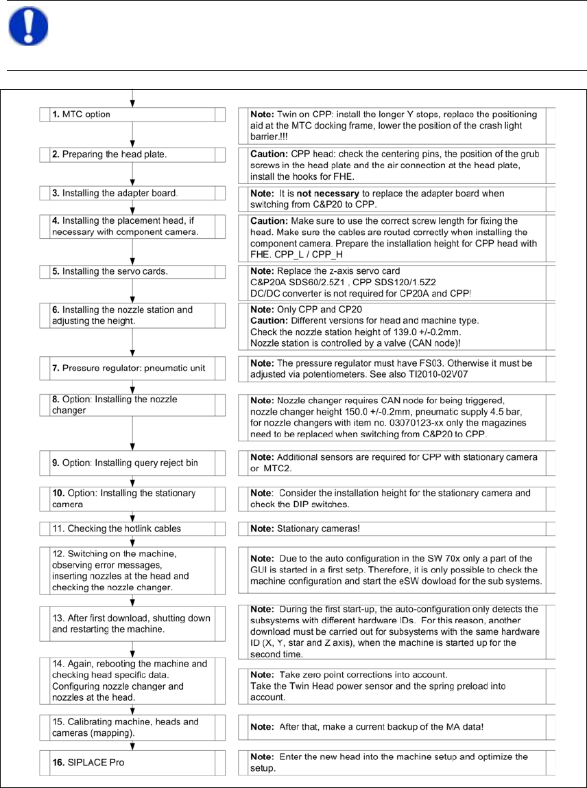
2.6.1 Installing the Placement Head - Procedure
NOTE:
This flow chart describes the basic procedure for switching between different placement
head types on X series machines with SW 70x and X tables. 2
2 Assembly Instructions Head Reconfiguration Kit CPP for the SIPLACE X Series Head Reconfiguration Kit
2.6 Replacing the Placement Head - Procedure Issue 03/2010
78
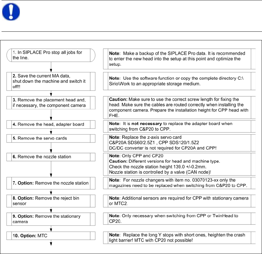
2.6.2 Removing the Placement Head - Procedure
2
NOTE:
This flow chart describes the basic procedure for switching between different placement
head types on X series machines with SW 70x and X tables. 2

Head Reconfiguration Kit 2 Assembly Instructions Head Reconfiguration Kit CPP for the SIPLACE X Series
Issue 03/2010 2.7 Installing the CPP Placement Head
79
2.7 Installing the CPP Placement Head
The CPP placement head can only be used together with a component trolley docking unit of the
X-series and X-feeder modules. 2
2.7.1 CPP with MTC2 Option
2
– When an MTC is present, the head must be installed in the high position. The installation height
is monitored during the head reference run.
– In SW 702, the CPP head is not released for a two-gantry placement area with MTC. In this
configuration, there is no nozzle changer available at the location with the MTC.
NOTE:
For further information on MTC2, please refer to the Assemby Instructions "MTC2 on
Component Trolley Docking Unit, X-S" [00194725-xx] and the Installation Instructions
"MTC2 on SIPLACE HF" [00193897-xx]. 2