00196428-0102_AI_Reconfig_Kit_X-Serie_CPP_DE EN - 第84页
2 Assembly Instructions Head Reconfiguration Kit CPP for the SIPLACE X Series Head Reconfiguration Kit 2.7 Installing the CPP Placement Head Issue 03/2010 84 X If the pins protrude too far , proceed as follows: – Chuck i…
Head Reconfiguration Kit 2 Assembly Instructions Head Reconfiguration Kit CPP for the SIPLACE X Series
Issue 03/2010 2.7 Installing the CPP Placement Head
83
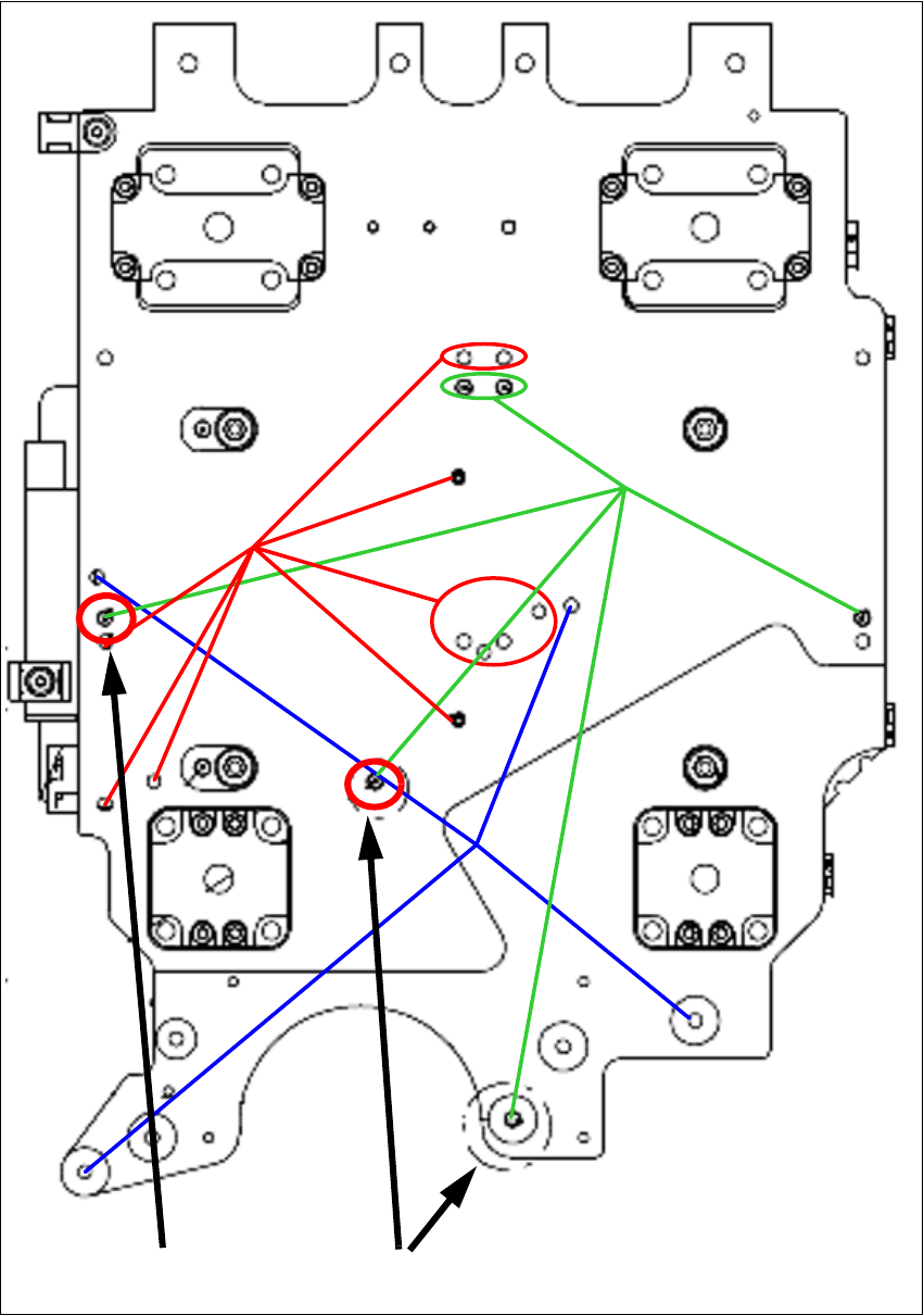
fig. 2.7.1 Scheme of the CFK06 head plate
4 screws to fix
the CPP head
All index pins
for C&P, CPP
and Twin head
Sealing
head plate
4.5 -0.2 mm
4.0 - 0.2 mm
2 Assembly Instructions Head Reconfiguration Kit CPP for the SIPLACE X Series Head Reconfiguration Kit
2.7 Installing the CPP Placement Head Issue 03/2010
84
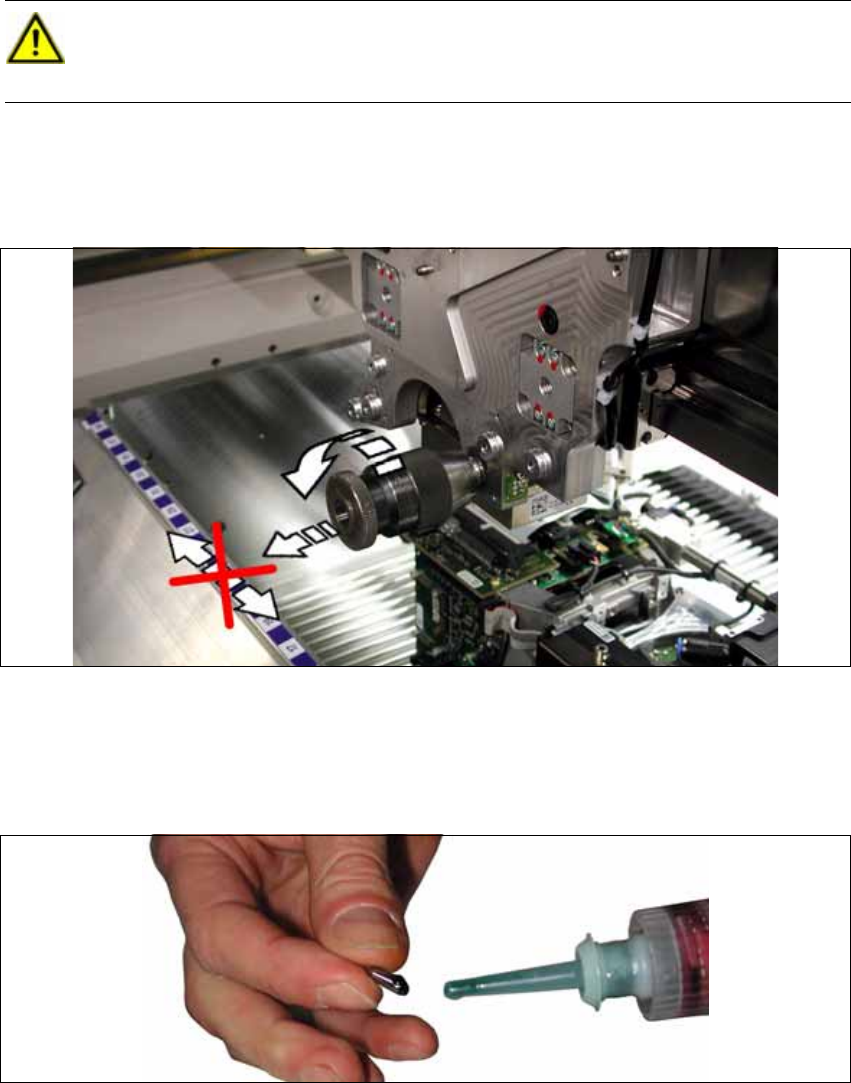
X If the pins protrude too far, proceed as follows:
– Chuck in the pin with the 0-6.5 drill chuck (removing the head pin) [03075733-xx].
– First loosen the pin by rotating the drill chuck.
– Now, pull the pin out of the head plate by rotating the drill chuck at the same time.
No shear forces must be exerted on the pin.
X Manually insert the new pins into the respective holes to check, if they fit. The hole at the head
plate is a dowel hole. The pin should sit backlash-free in the hole.
X Cover the new "DIN 6325 - 4 M6 x 10-ST" [00331299-xx] pin with Loctite 601 from the package
[00303394-xx].
CAUTION:
Place the drill chuck vertically! Lift the pin off vertically!
Do not scratch the head plate! Should it get scratched, grind the scratch carefully! 2
Head Reconfiguration Kit 2 Assembly Instructions Head Reconfiguration Kit CPP for the SIPLACE X Series
Issue 03/2010 2.7 Installing the CPP Placement Head
85
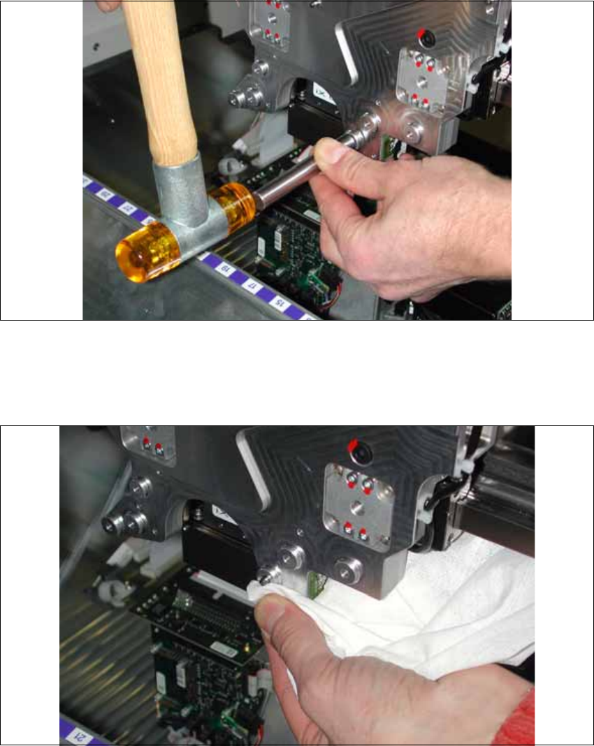
X Hammer the pins vertically into the head plate until the stop using the testing tool for pin length
4-(0.2) [03075779-xx] and a rubber hammer.
X If the adjustment aid lays flush without clearance on the head plate, the pin has been driven in
far enough.
X Remove excess Loctite 601 from the pin and the head fixture plate using a lint-free cloth.
X Replace the sealing screw according to fig. 2.7.1, Scheme of the CFK06 head plate.
Cover the sealing screws with locking varnish. Remove excess varnish with a lint-free cloth.