00196428-0102_AI_Reconfig_Kit_X-Serie_CPP_DE EN - 第90页
2 Assembly Instructions Head Reconfiguration Kit CPP for the SIPLACE X Series Head Reconfiguration Kit 2.7 Installing the CPP Placement Head Issue 03/2010 90 2.7.4 Inst alling the Placement Head 2.7.4.1 Inst alling the C…
Head Reconfiguration Kit 2 Assembly Instructions Head Reconfiguration Kit CPP for the SIPLACE X Series
Issue 03/2010 2.7 Installing the CPP Placement Head
89
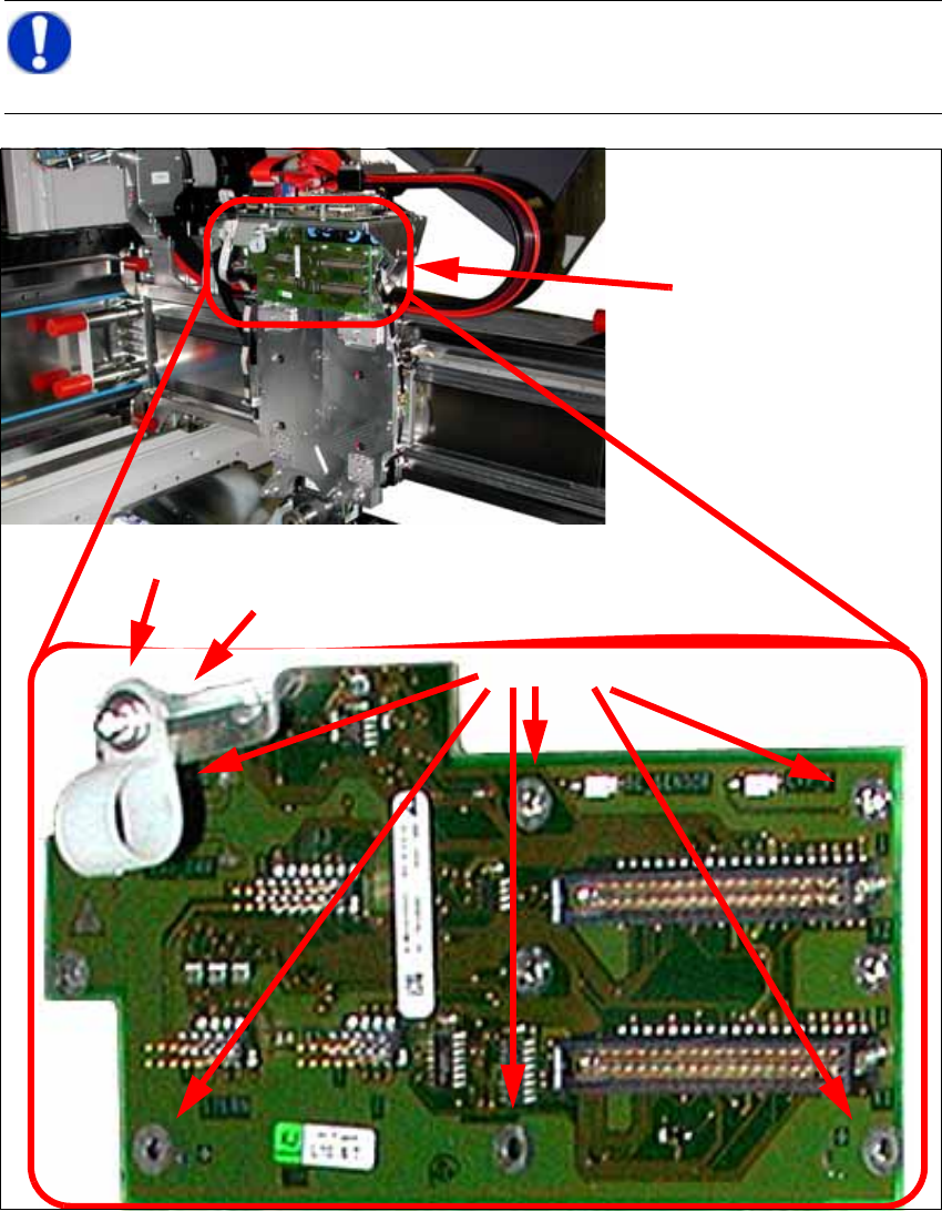
2.7.3 Installing the Adapter Board
X Connect the CPP/A364 PCB/Head adapter [03077980-xx] to the head interface and fix the
board with 6 DIN912 M3x6 - A2 screws [00201463-xx] to the head plate.
2
NOTE:
When switching from C&P20 to CPP the head board must not be changed. However, the
cable holder must be detached for the CPP. 2
Head adapter board
6 screws
Cable clip
Hexagonal bolt
2 Assembly Instructions Head Reconfiguration Kit CPP for the SIPLACE X Series Head Reconfiguration Kit
2.7 Installing the CPP Placement Head Issue 03/2010
90
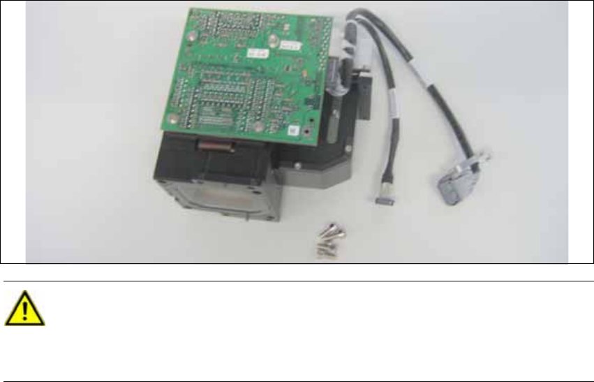
2.7.4 Installing the Placement Head
2.7.4.1 Installing the Component Camera
2
CAUTION:
Use the universal head stand [00363290-xx] when installing the camera. 2
Never place the head onto the component sensor, because in doing so you risk dama-
ging it. 2
Head Reconfiguration Kit 2 Assembly Instructions Head Reconfiguration Kit CPP for the SIPLACE X Series
Issue 03/2010 2.7 Installing the CPP Placement Head
91
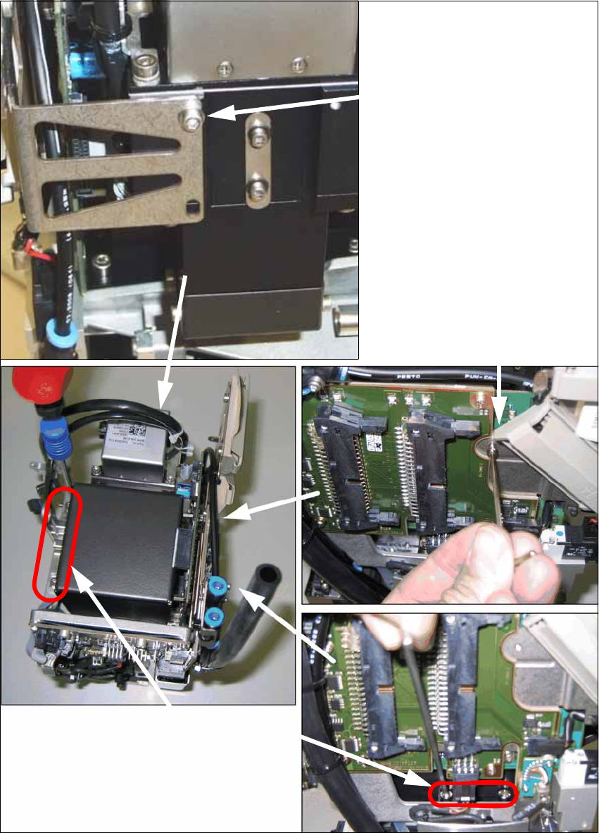
X Install the component camera with the 4 screws at the CPP head and with one screw at the
board holder.
Screw at the board holder
DIN 912-M2,5 x 12-A2-70
[00304134-xx]
DIN 125-A 2.7-140HV-A2
[00201583-xx]
4 screws at the camera foot
DIN 912-M3 x 16-A2-70
[00325349-xx]
(in camera package)
Screw on the mounting bracket
DIN 912-M2,5x12-A2-70
[00304134-xx]
DIN 125-A 2.7-140HV-A2
[00201583-xx]