00196428-0102_AI_Reconfig_Kit_X-Serie_CPP_DE EN - 第91页
Head Reconfiguration Kit 2 Assembly Instructions Head Reconfiguration Kit CPP fo r the SIPLACE X Ser ies Issue 03/2010 2.7 Installing the CPP Placement H ead 91 X Install the component ca mera with the 4 screws at the CP…
2 Assembly Instructions Head Reconfiguration Kit CPP for the SIPLACE X Series Head Reconfiguration Kit
2.7 Installing the CPP Placement Head Issue 03/2010
90
2.7.4 Installing the Placement Head
2.7.4.1 Installing the Component Camera
2
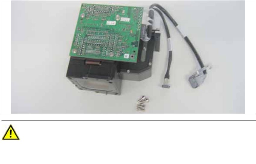
CAUTION:
Use the universal head stand [00363290-xx] when installing the camera. 2
Never place the head onto the component sensor, because in doing so you risk dama-
ging it. 2
Head Reconfiguration Kit 2 Assembly Instructions Head Reconfiguration Kit CPP for the SIPLACE X Series
Issue 03/2010 2.7 Installing the CPP Placement Head
91
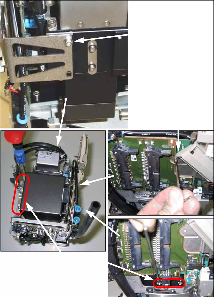
X Install the component camera with the 4 screws at the CPP head and with one screw at the
board holder.
Screw at the board holder
DIN 912-M2,5 x 12-A2-70
[00304134-xx]
DIN 125-A 2.7-140HV-A2
[00201583-xx]
4 screws at the camera foot
DIN 912-M3 x 16-A2-70
[00325349-xx]
(in camera package)
Screw on the mounting bracket
DIN 912-M2,5x12-A2-70
[00304134-xx]
DIN 125-A 2.7-140HV-A2
[00201583-xx]
2 Assembly Instructions Head Reconfiguration Kit CPP for the SIPLACE X Series Head Reconfiguration Kit
2.7 Installing the CPP Placement Head Issue 03/2010
92
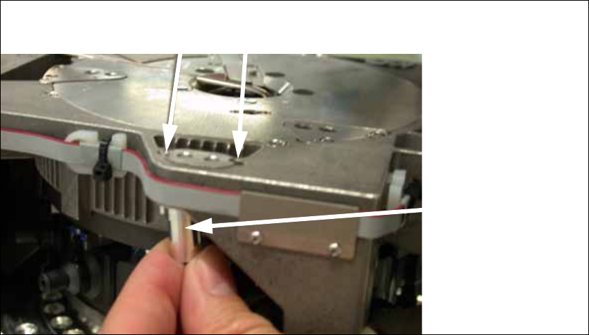
2.7.4.2 Preparing the Head for the Installation Height
X Prepare the head for its required installation height. The four bushings and the retaining
bracket must be fixed in their correct top or bottom position.
Should it be necessary to replace the bushings, loosen the fixing screws of the bushings and
place the bushing at its correct position (top or bottom). Carry out this step for all four fixing
bushings and the holding bracket of the head.
2
Holes for the fixing screws of the bushings 2
bushing 2
top 2
bottom2