00196428-0102_AI_Reconfig_Kit_X-Serie_CPP_DE EN - 第94页
2 Assembly Instructions Head Reconfiguration Kit CPP for the SIPLACE X Series Head Reconfiguration Kit 2.7 Installing the CPP Placement Head Issue 03/2010 94 Head low Head high Fixing ho les with bushings Retaining brack…
Head Reconfiguration Kit 2 Assembly Instructions Head Reconfiguration Kit CPP for the SIPLACE X Series
Issue 03/2010 2.7 Installing the CPP Placement Head
93
2
CAUTION:
The placement head can be installed at two different heights. CPP_L corresponds to a
component height of 6 mm. CPP_H corresponds to a height of 11.5 mm.
If the CPP head is used in a placement area with a stationary camera, a TwinHead or an
MTC, it must be installed in the high position only. 2
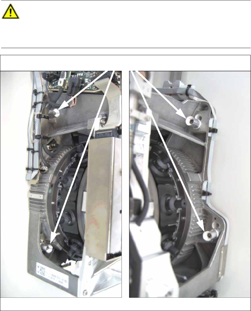
Head screws (here in "head high" position)
on the left on the right
2 Assembly Instructions Head Reconfiguration Kit CPP for the SIPLACE X Series Head Reconfiguration Kit
2.7 Installing the CPP Placement Head Issue 03/2010
94
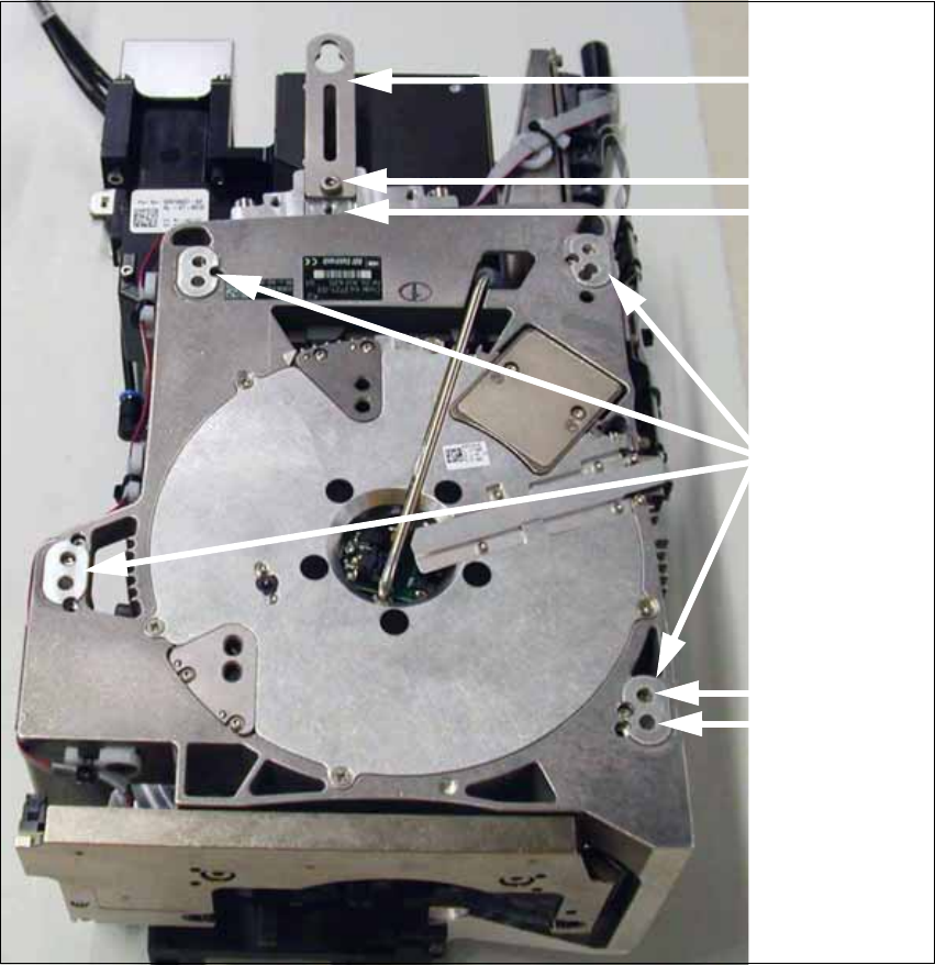
Head low
Head high
Fixing holes with
bushings
Retaining
bracket
Head low
Head high
Head Reconfiguration Kit 2 Assembly Instructions Head Reconfiguration Kit CPP for the SIPLACE X Series
Issue 03/2010 2.7 Installing the CPP Placement Head
95
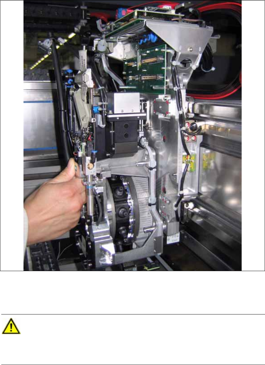
2.7.4.3 Installing the Placement Head
X Hang the placement head with its retaining bracket onto the corresponding hook at the gantry.
X Connect the two flat ribbon cables of the cable set CPP/X-Series [03074061-xx] to the con-
version board PCB/Head adapter CPP/A364 [03077980-xx]. Depending on the camera type,
this is not possible after the head screws have been tightened.
CAUTION:
The left cable at the head belongs to the bottom plug at the head adapter. The right cable
at the head belongs to the top plug at the head adapter. The cables are "intertwined".
Otherwise the machine stops with an error during startup. In some cases, machine parts
may be destroyed. 2