00196428-0102_AI_Reconfig_Kit_X-Serie_CPP_DE EN - 第97页
Head Reconfiguration Kit 2 Assembly Instructions Head Reconfiguration Kit CPP fo r the SIPLACE X Ser ies Issue 03/2010 2.7 Installing the CPP Placement H ead 97 X Connect the two plugs of the component camera. X Position…
2 Assembly Instructions Head Reconfiguration Kit CPP for the SIPLACE X Series Head Reconfiguration Kit
2.7 Installing the CPP Placement Head Issue 03/2010
96
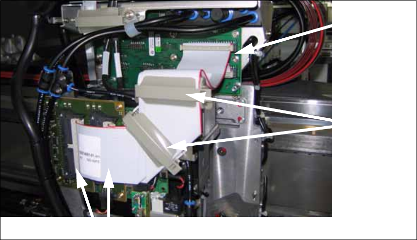
X Close the cable clips.
fig. 2.7.2 Flat ribbon cable at the CPP (here with camera type 28)
X Slightly lift off the placement head (0.5 mm), so that the head engages in its final position, and
hold it in this position.
X Tighten the 4 screws of the placement head.
Make sure to use the correct height, the correct screw lengths and the correct torque.: DIN912
M4x18 - 8.8 [00095023-xx], torque: 2.7 N
Close the cable
clips
Connect the top
and bottom plug
at the head
adapter
Connect the left and right plug at the head
Head Reconfiguration Kit 2 Assembly Instructions Head Reconfiguration Kit CPP for the SIPLACE X Series
Issue 03/2010 2.7 Installing the CPP Placement Head
97
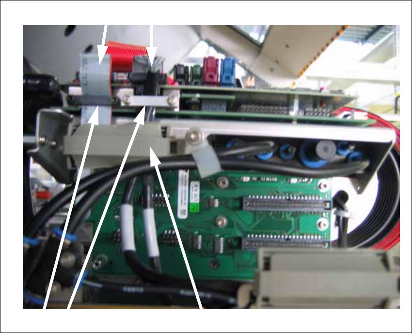
X Connect the two plugs of the component camera.
X Position the securing bracket in place and fix them with the screws.
X Close the cable clip.
2
Closing the cable clip
Connecting the plugs
Securing brackets
2 Assembly Instructions Head Reconfiguration Kit CPP for the SIPLACE X Series Head Reconfiguration Kit
2.7 Installing the CPP Placement Head Issue 03/2010
98
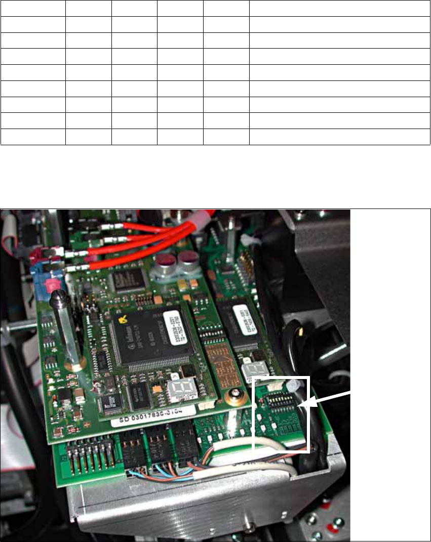
2.7.4.4 Settings of the Head Interface Board C500
X Check the jumper settings on the head interface board C500:
2
X In case of CAN bus problems, measure the resistance between pin 7 (CAN High) and pin 2
(CAN Low). It should be 60 Ohm.
2
Jumper Gantry 1 Gantry 2 Gantry 3 Gantry 4
1 0 1 0 1 Gantry ID0
2 0 0 1 1 Gantry ID1
3 1 1 1 1 120 Ohm CAN terminating resistor
4 0 0 0 0 Boot
5 0 0 0 0 Reset
6 0 0 0 0 CAN-ID0
7 0 0 0 0 CAN-ID1
8 0 0 0 0 Write protection released
Position of
the jumpers