4Q4CEIM - 第21页
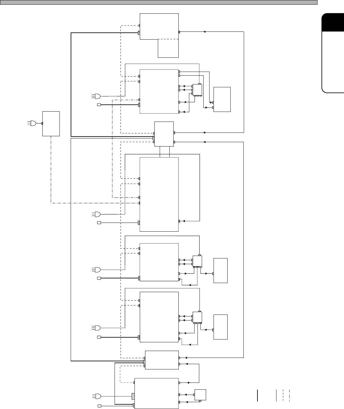
Page 1-9 INST ALLA TION 1 Preparations for Installation 4Q4C-E-IMA01-A01-01 4Q4C-002E TB 200V 230V 200V POUT PIN LD12F RV10C SP28P TB 100V 400V 400V 200V 200V Atomosphere temperature control unit POUT CN01 CN00 CN01 M.T …

Page 1-8
Preparations for Installation
1-1-7 Length of Cables
It is unnecessary to connect with other products except followings:
Ready and Stop line signals
Ethernet signals
AC power
The line signals are actually not connected with the machine system.
This means that this machine system is totally separated from the system of the surrounding
devices.
Attached communication specifications
The length of the line signal cable used for the machine (series) is less than 3 m, so no further
testing of these cables is required.
The length of Ethernet signal cable used for the machine (series) is less than 10 m.
The length of AC power cable used for the machine is less than 7 m.
(Use the shielding wire for AC power cable.)
4Q4C-E-IMA01-A01-00
Page 1-9
INSTALLATION
1
Preparations for Installation
4Q4C-E-IMA01-A01-01
4Q4C-002E
TB
200V
230V
200V
POUT
PIN
LD12F RV10C
SP28P
TB
100V
400V
400V
200V
200V
Atomosphere
temperature
control unit
POUT
CN01CN00
CN01
M.T
200V
CN00
M.T
CN01 CN00 CN01
M.T
BD20S CM201/202
CN00 CN01
TB
100V
400V
400V
200V
100V
MC12C
CN00 CN01
PIN
200V
POUT
200V
M.T
CM120
CN00 CN01
TB
100V
200V
400V
400V
400V
LD12B
200V
PIN
CN00
200V
100V
A10
A3
DT20F
-20U
3 400V
Atomosphere
temperature
control unit
φ
3 400V
φ
3 400V
φ
3 400V
φ
1 230V
φ
: Air
: Main terminal
: Transmission box
: Power
: Line signal
: Ethernet
M.T
TB
PT
1 230V
φ
Page 1-10
1-2 Installing Procedure
NOTICE
Machine installation is conducted by experts.
Here, the outline of the procedure is described.
For rearranging the machine, make contact with the service department.
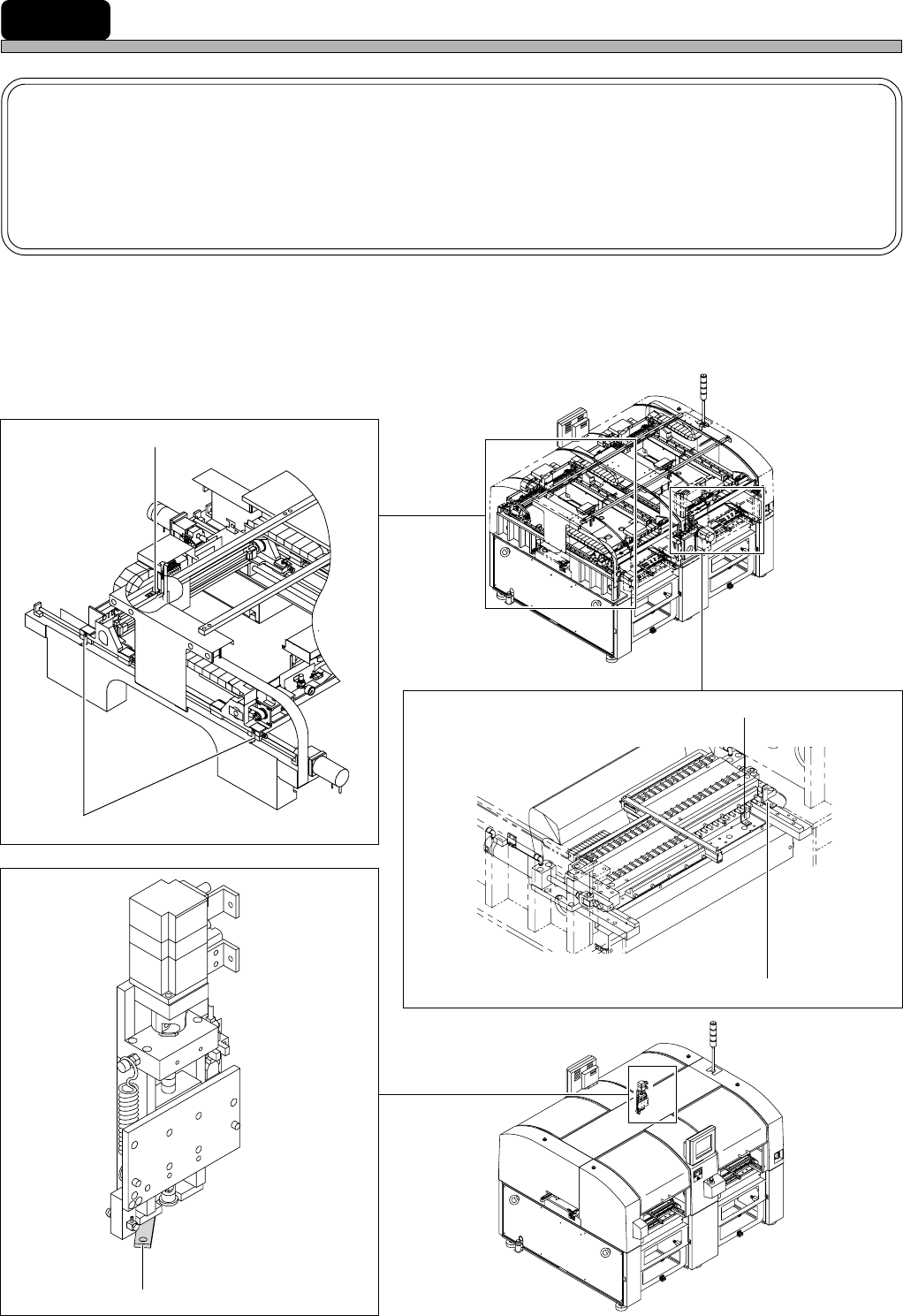
1) Machine transport condition
During the machine transport, X-axis, Y-axis, Z-axis, feeder base drawer, and sending cylinder
changer (it is for the double feeder) are fixed with the fixing brackets (red) to prevent removing.
∗ Half number of fixing brackets is necessary for CM201.
4Q4C-E-IMA01-A01-01
4Q4C-010CC0
4Q4C-011AC0
4U4C-150FC1
4Q4C-904E
4U4C-AC00
X-axis fixing brackets (4 points)
Y-axis fixing brackets (8 points)
Z-axis fixing brackets (4 points)
Fixing brackets for sending cylinder changer (4 points) (option)
Fixing brackets for feeder base drawer (8 points)