00194591_02.pdf - 第43页
Installation Manual SIPLACE Setup Center RF 2.1 3 Installation Edition 09/2005 EN 3.3 Installation of SIPLACE Setup Center and Possible Setup Types 43 3 3 Aiming pointer (st andard is 300 ms). The aiming poin ter holds t…
3 Installation Installation Manual SIPLACE Setup Center RF 2.1
3.3 Installation of SIPLACE Setup Center and Possible Setup Types Edition 09/2005 EN
42
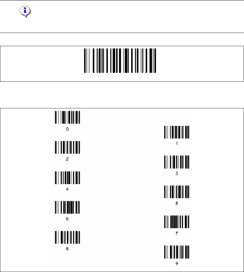
3.3.3.8 Setting of the Scanner Address
Each scanner requires a unique address.
→ Enter the following barcode and scan the four digits for the scanner address, e.g. '0' '0' '0' '1'.
Note
The address must consist of four digits. Don't forget to enter heading zeros. 3
3
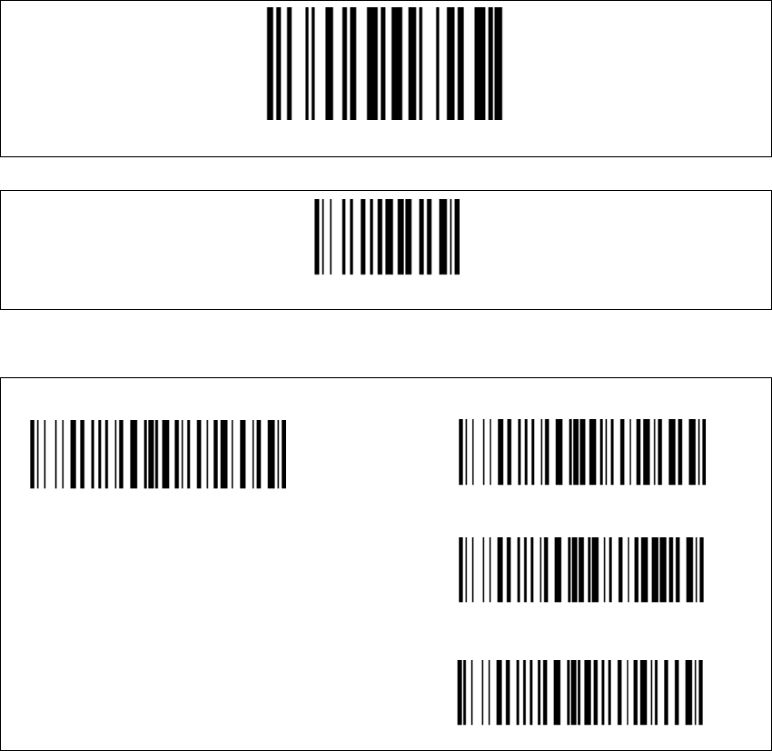
Four digits for the DRAGON ™ M Address (from 0000 to 1999)
3
Set Radio Address
Installation Manual SIPLACE Setup Center RF 2.1 3 Installation
Edition 09/2005 EN 3.3 Installation of SIPLACE Setup Center and Possible Setup Types
43
3
3
Aiming pointer (standard is 300 ms). The aiming pointer holds the laser beam on a single spot
before reading a barcode. 3
3
3
The scanner is now ready configured. Now it needs to be bound to a RF station as described
below. 3
Barcode Type Code 93
Exit and Save configuration
300ms
500ms
1 sec
Aiming system disabled
3 Installation Installation Manual SIPLACE Setup Center RF 2.1
3.3 Installation of SIPLACE Setup Center and Possible Setup Types Edition 09/2005 EN
44
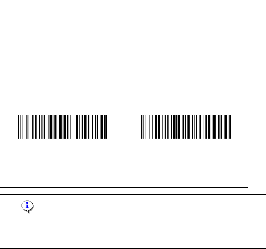
3.3.3.9 Bind or Join the scanner to a RF station
You can connect more than one scanner to one RF station. With the first scanner you need to scan
the barcode label Bind, with all further scanners you need to scan the barcode label Join. 3
Please follow one of the following instructions according to your choice. 3
3
Note
You can never recognize if the Dragon scanner has the configuration Bind or Join. Therefore
please note your configuration you did. If you do not remember your configuration you have to
configure it once again. 3
Bind
→ Make sure the RF station is on (yellow
light is on).
→ When scanning the following barcode
the green LED of the scanner is active for
about 10 seconds. Put the scanner into
the RF station during these 10 seconds.
Join
→ The following barcode may be used to
add further scanners to one RF station.
→ Keep in mind that the first scanner need
to be bound to the station as described
on the left side. Each scanner must be
set to a unique address (see “Setting of
the Scanner Address” on page 42).
The connection can be tested by scanning
any barcode with the scanner. After the scan-
ning, the yellow LED ”power/data” is
switched off for 0.5 seconds.
Bind
Join