00196962-04-BA-SX12-V2-EN.pdf - 第124页
3 Technical data and assemblies User manual SIPLACE SX1/SX2 3.6 Gantry system From software version SC 706.1 SP1 Version 10/2014 124 3.6 Gantry system The gantry system of the SIPLAC E SX1/SX2 machines is a so-calle d H …
User manual SIPLACE SX1/SX2 3 Technical data and assemblies
From software version SC 706.1 SP1 Version 10/2014 3.5 Placement head
123
3.5.5.2 Technical data
SIPLACE TwinStar (TH)
with component camera type 33
(fine pitch camera)
with component camera type 25
(flip chip camera)
Component range
*a
0402 to SO, PLCC, QFP, BGA, special
components, bare dies, flip-chips
0201 to SO, PLCC, QFP, sockets,
plugs, BGA, special components, bare
dies, flip-chips, shields
Component specs
*b
Max. height
*c
Min. lead pitch
Min. lead width
Min. ball pitch
Min. ball diameter
Min. dimensions
Max. dimensions
Max. weight
*d
25 mm
0.3 mm
0.15 mm
0.35 mm
0.2 mm
1.0 mm x 0.5 mm
55 mm x 45 mm (single measurement)
For use with two nozzles:
50 mm x 50 mm or 69 mm x 10 mm
For use with one nozzle (multiple measure-
ment):
78 mm x 78 mm or 110 mm x 10 mm
up to 200 mm x 125 mm (with restrictions)
100 g
25 mm
0.25 mm
0.1 mm
0.14 mm
0.08 mm
0.6 mm x 0.3 mm
16 mm x 16 mm (single measurement)
55 mm x 55 mm (multiple measure-
ment)
100 g
Programmable set-down
force
1.0 N - 15 N
2.0 N - 70 N
*e
1.0 N - 15 N
2.0 N - 70 N
e
Nozzle types
*f
5xx (standard)
4xx + adapter
8xx + adapter
9xx + adapter
gripper
5xx (standard)
4xx + adapter
8xx + adapter
9xx + adapter
gripper
Nozzle spacing for P&P
heads
70.8 mm 70.8 mm
X/Y accuracy
*g
± 26 µm / 3σ, ± 35 µm / 4σ ± 22 µm / 3σ, ± 30 µm / 4σ
Angular accuracy ± 0.05° / 3σ, ± 0.07°/ 4σ ± 0.05° / 3σ, ± 0.07° / 4σ
Illumination level 6 6
Possible illumination level
settings
256
6
256
6
*)a Please note that the placeable component range is also affected by the pad geometry, the customer-specific standards, the
component packaging tolerances and the component tolerances.
*)b If the MultiStar and TwinStar are combined in the same placement area, the maximum component height may be restricted .
*)c Max. component height 45 mm available on request, with Very High Force Pick&Place (VHF) and nozzle type 508.
*)d If standard nozzles are used
*)e SIPLACE Very High Force Twin Star (VHF TH).
*)f Over 300 different nozzles and 100 gripper types are available, with an extensive nozzle database available online.
*)g The SIPLACE benchmark value is measured during the machine acceptance tests. It corresponds to the conditions set out
in the SIPLACE scope of service and supply.
3 Technical data and assemblies User manual SIPLACE SX1/SX2
3.6 Gantry system From software version SC 706.1 SP1 Version 10/2014
124
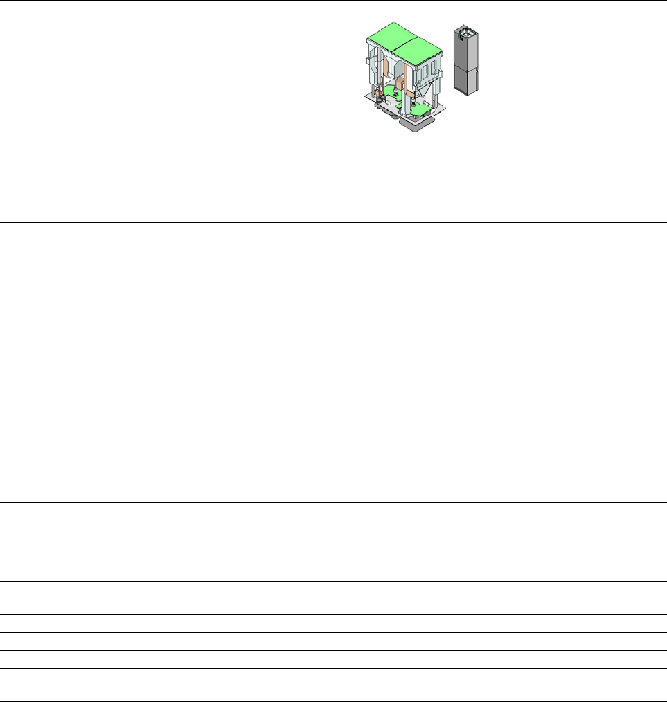
3.6 Gantry system
The gantry system of the SIPLACE SX1/SX2 machines is a so-called H gantry. This consists of
two Y axes which are driven from both sides by linear motors. The X axis is driven by one linear
motor. The H gantry runs over a fixed and a loose bearing along the bearing surface of the two Y
axes. These surfaces are at an angle of 45° to the gantry. The linear scales for the Y measuring
system are located under these bearing surfaces. In the SIPLACE SX, the gantries have the same
design and can be equipped with either one or two gantries. In the SIPLACE SX2, gantries 1 and
2 are fitted at an angle of 180°. The placement heads are fitted to the inside of the gantry.
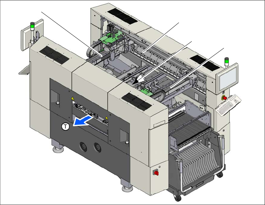
3.6.1 Gantry positions
3
Fig. 3.6 - 1 Position of gantries in the SX2 machines
(1) X axis, gantry 1
(2) Y axis, gantry 1 and gantry 2
(3) Y axis, gantry 1 and gantry 2 (concealed)
(4) X axis, gantry 2
(T) Direction of PCB transport
(1)
(2)
(4)
(3)
User manual SIPLACE SX1/SX2 3 Technical data and assemblies
From software version SC 706.1 SP1 Version 10/2014 3.6 Gantry system
125
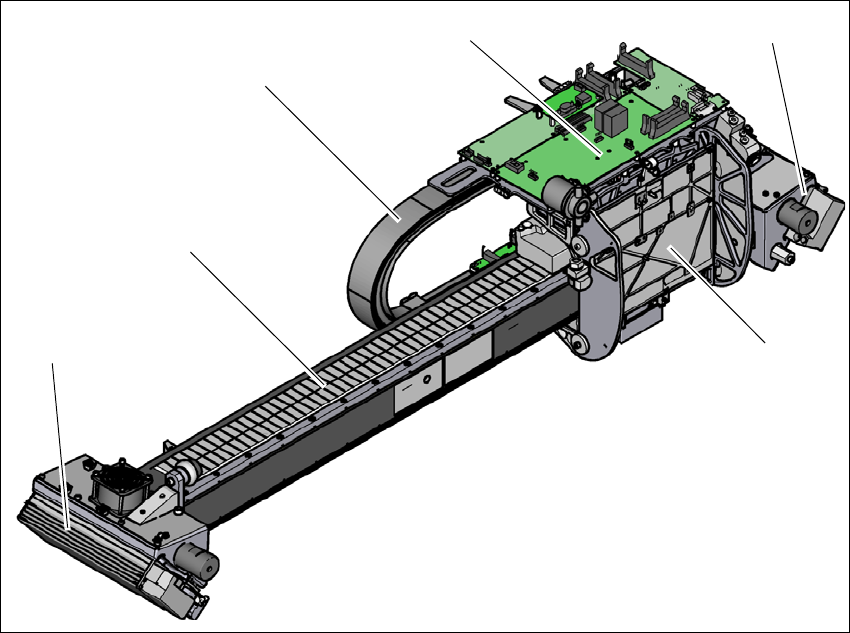
3.6.2 X axis structure
3
Fig. 3.6 - 2 Design of X axis - view of head mount
(1) Head mount with X axis linear motor (primary part)
(2) Y linear motor 2 with fixed bearing (primary part) and fan
(3) Guidance system with permanent magnet (secondary part of the X linear motor)
(4) Trailing cable
(5) Head board with Head Control Unit
(6) Y linear motor 1 with loose bearing (primary part) and fan
(4)
(3)
(1)
(5)
(2)
(6)