00196962-04-BA-SX12-V2-EN.pdf - 第16页
1 Introduction User manual SIPLACE SX1/SX2 1.1 SIPLACE SX1/SX2 From software version SC 706.1 SP1 Version 10/2014 16 The SIPLACE SX1 and SX2 plac ement machine s demonstrate – High precision , – High configuration flexib…
User manual SIPLACE SX1/SX2 1 Introduction
From software version SC 706.1 SP1 Version 10/2014 1.1 SIPLACE SX1/SX2
15
1 Introduction
This operating guide is a manual or reference work for operating and setting up the SIPLACE
®
SX1/SX2 placement machines. This document is the original user manual.
The header of each chapter contains the release and software version, to which this manual ap-
plies.
1.1 SIPLACE SX1/SX2
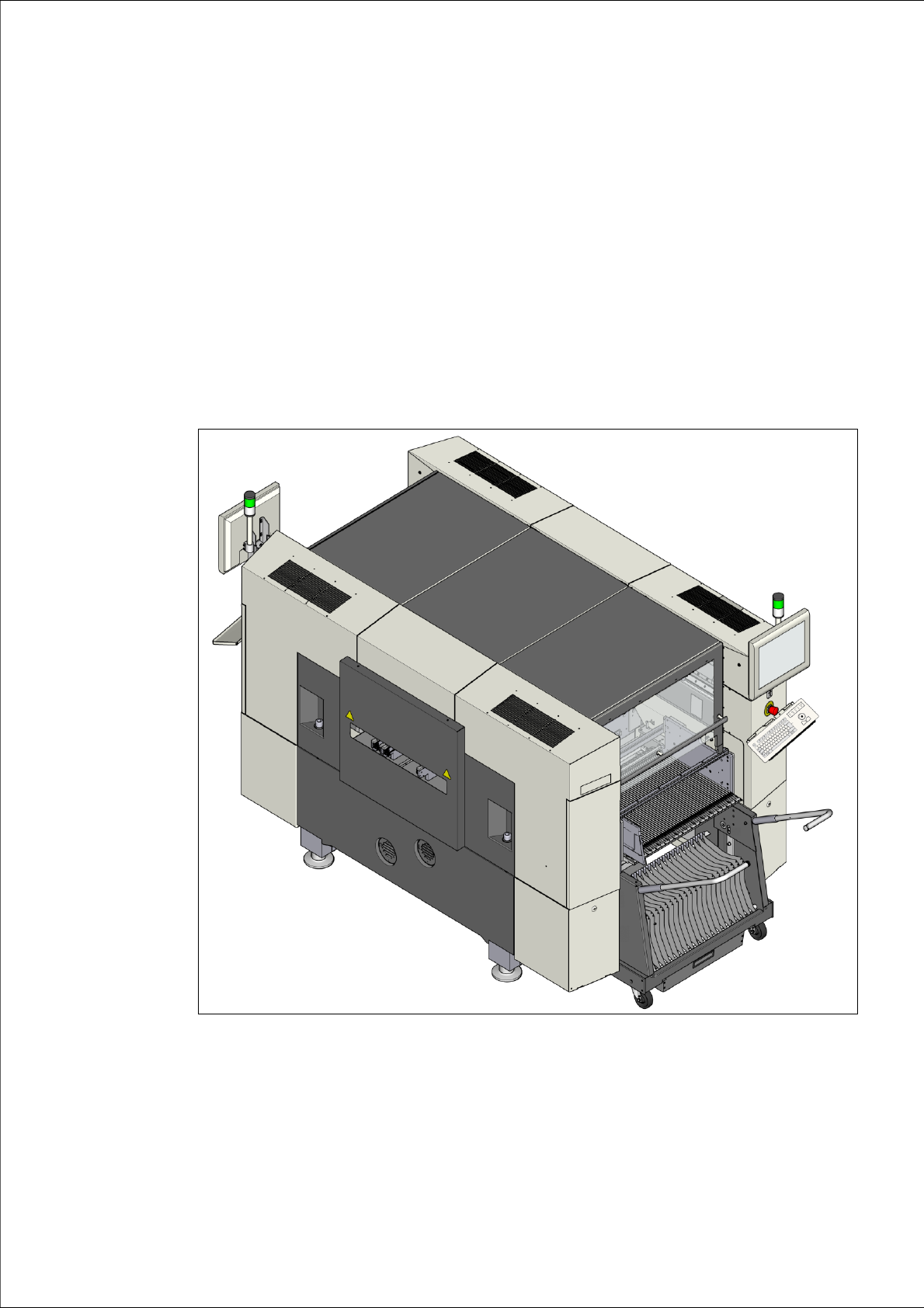
1
Fig. 1.1 - 1 SIPLACE SX1/SX2 placement machine

1 Introduction User manual SIPLACE SX1/SX2
1.1 SIPLACE SX1/SX2 From software version SC 706.1 SP1 Version 10/2014
16
The SIPLACE SX1 and SX2 placement machines demonstrate
– High precision,
– High configuration flexibility,
– Head and gantry modularity
– Placement performance up to the high end process range and
– A wide ranging component range from 03015 components to a size of
125 mm x 10 mm.
Three placement methods are possible for processing the components:
– Collect&Place,
– Pick&Place and
– A combination of Collect&Place and Pick&Place (mixed mode).
The SIPLACE SX1 placement machine consists of one gantry while the SIPLACE SX2 placement
machine has two gantries. The head and gantry modularity principle developed by SIPLACE al-
lows you to change placement heads and gantries quickly and easily. For an overview of the
placement head configuration, refer to section 1.1.1
from page 17.
These can be quickly and accurately positioned by linear motors, moving independently of one
another in the X and Y directions.
The SX1/SX2 machine supports use of either the SIPLACE single conveyor or the flexible dual
conveyor.
There are two locations available for supplying components. These can be fitted with component
trolleys and configured with up to 60 tracks.
Alternatively, you can also dock a waffle pack changer (WPC5 or WPC6) at each of the two loca-
tions. If a WPC5/WPC6 is set up at one of the locations, a component trolley with 30 tracks must
be configured for the other location.

User manual SIPLACE SX1/SX2 1 Introduction
From software version SC 706.1 SP1 Version 10/2014 1.1 SIPLACE SX1/SX2
17
1.1.1 Overview of placement head configuration
1
Machine Placement head Standard cameras Options
SIPLACE
SX1
C&P20 Component camera, type
23
– Component camera, type 41
CPP Component camera, type
30
– Stationary camera, type 33
TH Component camera, type
33
– Stationary camera, type 25 (only
at location 1)
SIPLACE
SX2
C&P20 / C&P20 Component camera, type
23
– Component camera, type 41
CPP / CPP
Component camera, type
30
– Stationary camera, type 33
CPP / TH
Component camera, type
30
Stationary camera, type 33
– Stationary camera, type 25 (only
at location 1)
TH / TH
Stationary camera, type 33 – Stationary camera, type 25 (only
at location 1)