00196962-04-BA-SX12-V2-EN.pdf - 第196页
4 Setting up and commissioning Us er ma nual SIPLACE SX1/SX2 4.2 Infrastructure at the installation location From software version SC 706.1 SP1 Version 10/2014 196 4.2.3.5 Connecting the power supply cable 4 Fig. 4.2 - 5…
User manual SIPLACE SX1/SX2 4 Setting up and commissioning
From software version SC 706.1 SP1 Version 10/2014 4.2 Infrastructure at the installation location
195
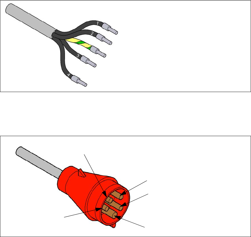
4.2.3.4 Mains connection - delivery configuration
The main power connection is configured according to the power supply of the country concerned.
– The machine is configured for voltages of 204V AC, 220V AC or 230V AC.
The machine has a mains power cable WITHOUT plug. 4
4
Fig. 4.2 - 3 Description of wires in the mains power cable
– The machine is configured for voltages of 380V AC, 400V AC or 415V AC.
The machine has a mains power cable WITH Cekon plug. 4
4
Fig. 4.2 - 4 Assignment in the Cekon plug
1 = (L1): three-phase
2 = (L2): three-phase
3 = (L3): three-phase
4 = (N): neutral conductor
green/yellow = (PE): conductor
PE
L1
L2
L3
N
4 Setting up and commissioning User manual SIPLACE SX1/SX2
4.2 Infrastructure at the installation location From software version SC 706.1 SP1 Version 10/2014
196
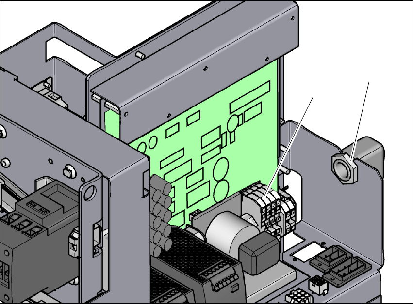
4.2.3.5 Connecting the power supply cable
4
Fig. 4.2 - 5 Terminal panel for connecting the power cable
(1) Terminal panel (X99)
(2) Cable fixtures
Crimp a ferrule onto each end of the wire.
Loosen the nuts on the cable fixture (2).
Run the mains power cable through the cable fixture (2) to the terminal panel X99 (1).
Fasten the cable to the terminal panel X99 (item 1).
(L1): three-phase 4
(L2): three-phase 4
(L3): three-phase 4
(N): neutral conductor 4
(PE): PE conductor 4
Make sure that the bending radius is adequate. The wires must not be kinked.
Manually tighten the cable fixture.
(1)
(2)
User manual SIPLACE SX1/SX2 4 Setting up and commissioning
From software version SC 706.1 SP1 Version 10/2014 4.2 Infrastructure at the installation location
197
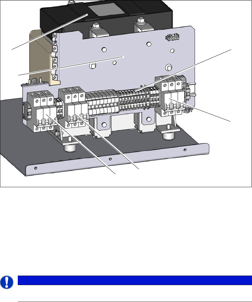
4.2.3.6 Checking connections to the primary side of the three-phase transformer T1
The primary side of the three-phase transformer must be configured for the relevant supply volt-
age.
Check the terminal panel (1) to make sure that the primary end of the three-phase transformer
(cable in item 2 ) is correctly connected for the relevant supply voltage.
4
Fig. 4.2 - 6 Terminal panel for the primary side of the three-phase transformer T1
(1) Terminal panel with primary connections for the three-phase transformer T1
(2) Fuse F5; 16A , characteristic C; for AC/DC converter and vacuum pump option
(3) Fuse F4; 25A , characteristic C; for cutter and PCB conveyor
(4) Fuse F3; 25A , characteristic C; for gantry axes (250 V-) and head axes (150 V-)
(5) Installation point for the electrics of the vacuum pump option
(6) Three-phase transformer
4
PLEASE NOTE
The supply networks for North Japan (3 x 200 V~) and for the USA (
3 x 208 V~) are connected to the terminals for 3 x 204 V~.
(1)
(2)
(3)
(4)
(6)
(5)