00196962-04-BA-SX12-V2-EN.pdf - 第308页
6 Station extensions User ma nual SIPLACE SX1/SX2 6.1 Nozzle changer From software version SC 706.1 SP1 Version 10/2014 308 6.1.4.2 T echnical data 6 6.1.4.3 Position of nozzle changer for the 12 segment C&P h ead in…
User manual SIPLACE SX1/SX2 6 Station extensions
From software version SC 706.1 SP1 Version 10/2014 6.1 Nozzle changer
307
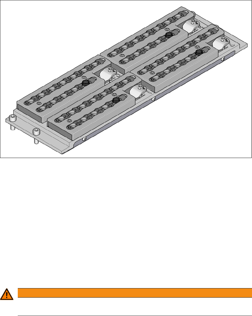
6.1.4 Nozzle changer for the 12 segment Collect&Place head
Item no. 00120604-xx Nozzle changer SX12 V2, C&P12 for position 1 or 2
6
Fig. 6.1 - 17 Nozzle changer for the 12 segment C&P head
6.1.4.1 Description
This nozzle changer can accommodate 4 magazines, each with 12 nozzle garages.
The magazines are seated on a common support. They are centered with two parallel pins and
fixed in place with 4 push buttons. The exact position is determined with two fiducials on each
magazine. The correct seat of the magazines on the basic nozzle changer body is monitored by
microswitches, to prevent a collision of the placement head with any magazines projecting up-
wards. All magazine locations must be filled since the safety circuit stops the machine in response
to missing magazines or magazines that are not seated correctly.
At the installed nozzle station, components can be blown off the nozzles of the SpeedStar and noz-
zles stripped off and rejected.
6
WARNING
The magazine for the 12 segment C&P head may only be used together with the 12
segment C&P head.
6 Station extensions User manual SIPLACE SX1/SX2
6.1 Nozzle changer From software version SC 706.1 SP1 Version 10/2014
308
6.1.4.2 Technical data
6
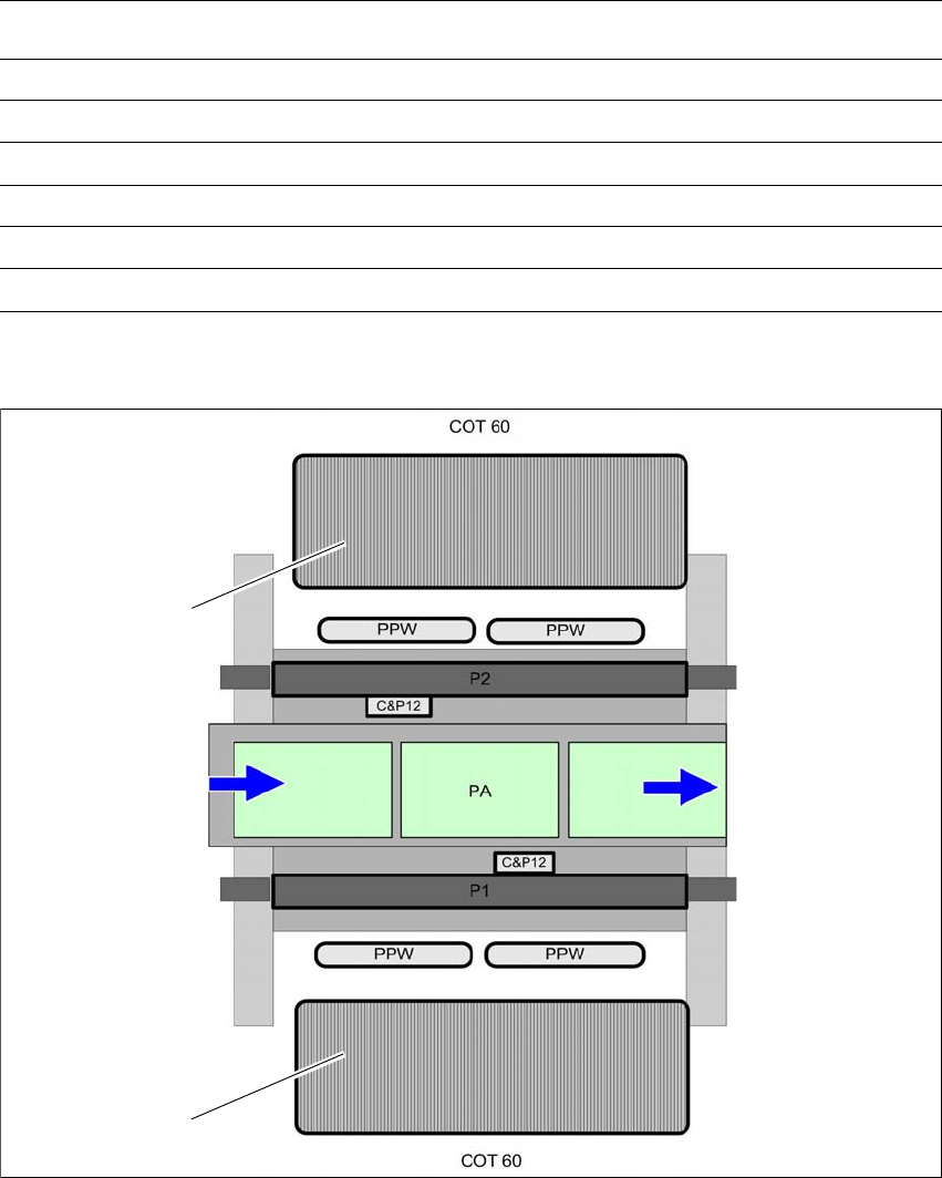
6.1.4.3 Position of nozzle changer for the 12 segment C&P head in the SX machine
6
Fig. 6.1 - 18 Position of nozzle changer for the 12 segment C&P head - example of SX2 shown
6
Nozzle changer for the SIPLACE 12 segment C&P head
Dimensions (length x width x height) 314 mm x 94.5 mm x 68.6 mm
Number of nozzle holders 48
Number of nozzle magazines 4
Nozzle types 3xxx
Nozzle changeover time Approx. 2s per nozzle
Compressed air connection 0.45 MPa (4.5 bar)
(1) Component trolley (PA) Placement area
(NC) Nozzle changer
(1)
(1)
User manual SIPLACE SX1/SX2 6 Station extensions
From software version SC 706.1 SP1 Version 10/2014 6.1 Nozzle changer
309
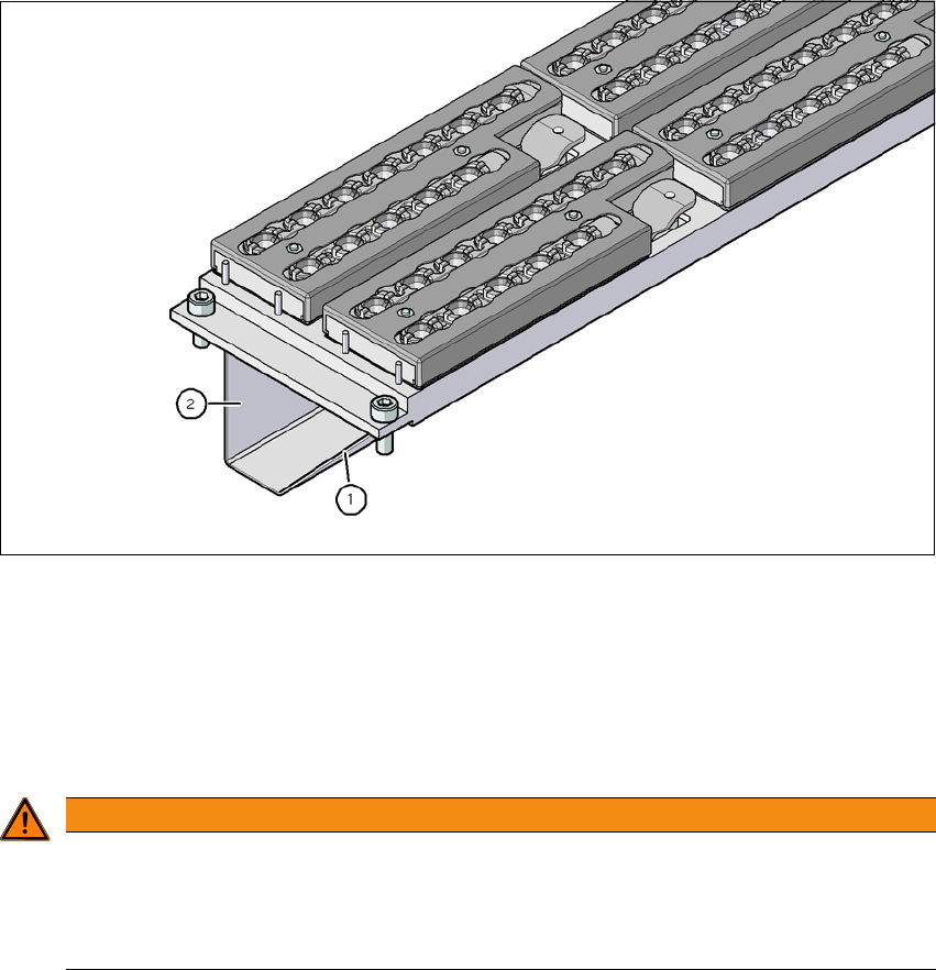
6.1.4.4 Assembly
In SX machines, the nozzle changers are fixed to the component trolley COT insert.
6
Fig. 6.1 - 19 Assembly position
(1) Sloping side points towards the component trolley COT insert
(2) Vertical side points towards the PCB conveyor
Align the nozzle changer so that the sloping side points towards the component trolley COT
insert.
6
WARNING
Risk of head crashes with mixed configurations!
There is a risk of head crashes with mixed configurations.
Only install the associated nozzle changer for each placement head, with the nozzle
magazines for the respective placement head.