00196962-04-BA-SX12-V2-EN.pdf - 第340页
6 Station extensions User ma nual SIPLACE SX1/SX2 6.10 SIPLACE 12 segment Collect&Place head From software version SC 706.1 SP1 Version 10/2014 340 6.10.3 T echnical dat a 6 12-segment Collec t&Place head place(C…
User manual SIPLACE SX1/SX2 6 Station extensions
From software version SC 706.1 SP1 Version 10/2014 6.10 SIPLACE 12 segment Collect&Place head
339
6
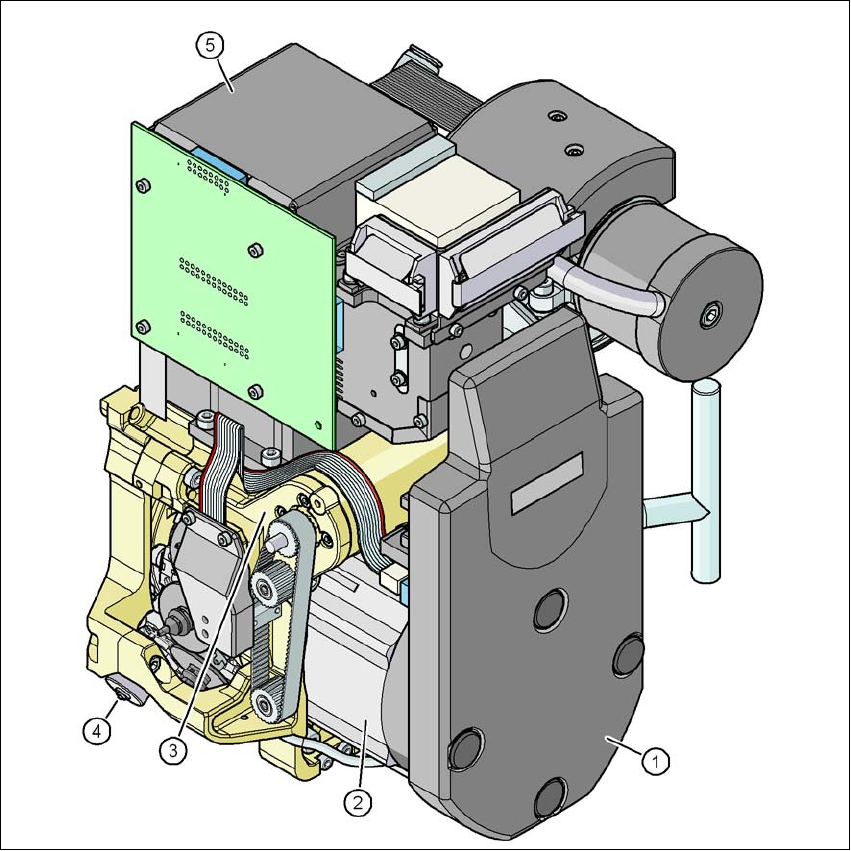
Fig. 6.10 - 2 12 segment Collect&Place head - function groups part 2
6
(1) Intermediate distributor board (under the cover)
(2) Star drive - DR motor
(3) Z axis motor
(4) Valve adjustment drive
(5) C&P component camera, type 30 (18 x 18) digital, high resolution (standard camera)
6 Station extensions User manual SIPLACE SX1/SX2
6.10 SIPLACE 12 segment Collect&Place head From software version SC 706.1 SP1 Version 10/2014
340
6.10.3 Technical data
6
12-segment Collect&Place head place(CP12)
with component camera type 30
Component range
*a
01005
*b
to Flip-Chip, Bare Die, PLCC44, BGA,
µBGA, TSOP, QFP, SO to SO32, DRAM
Component specification
Max. height
Min. lead pitch
Min. lead width
Min. ball pitch
Min. ball diameter
Min. dimensions
Max. dimensions
Max. weight
6 mm
0.3 mm
0.15 mm
0.25 mm
0.14 mm
0.4 mm x 0.2 mm
18.7 mm x 18.7 mm
2 g
Programmable
set-down force
Nozzle types 9xx
X/Y accuracy
*c
± 41 µm/3σ, ± 55 µm/4σ
Angular accuracy ± 0.5°/3σ, ± 0.7°/4σ
Component range 98,5%
Component camera type 30
Illumination level 5
Possible illumination level settings 256
5
*)a Please note that the component range that can be placed is also affected by the pad geometry, the customer-specific stan-
dards and the packaging tolerances.
*)b with 01005 package
*)c The SIPLACE benchmark value is measured during the machine acceptance tests. It corresponds to the conditions set out
in the SIPLACE scope of service and supply.
User manual SIPLACE SX1/SX2 6 Station extensions
From software version SC 706.1 SP1 Version 10/2014 6.11 Component camera for the TwinStar, FC camera
341
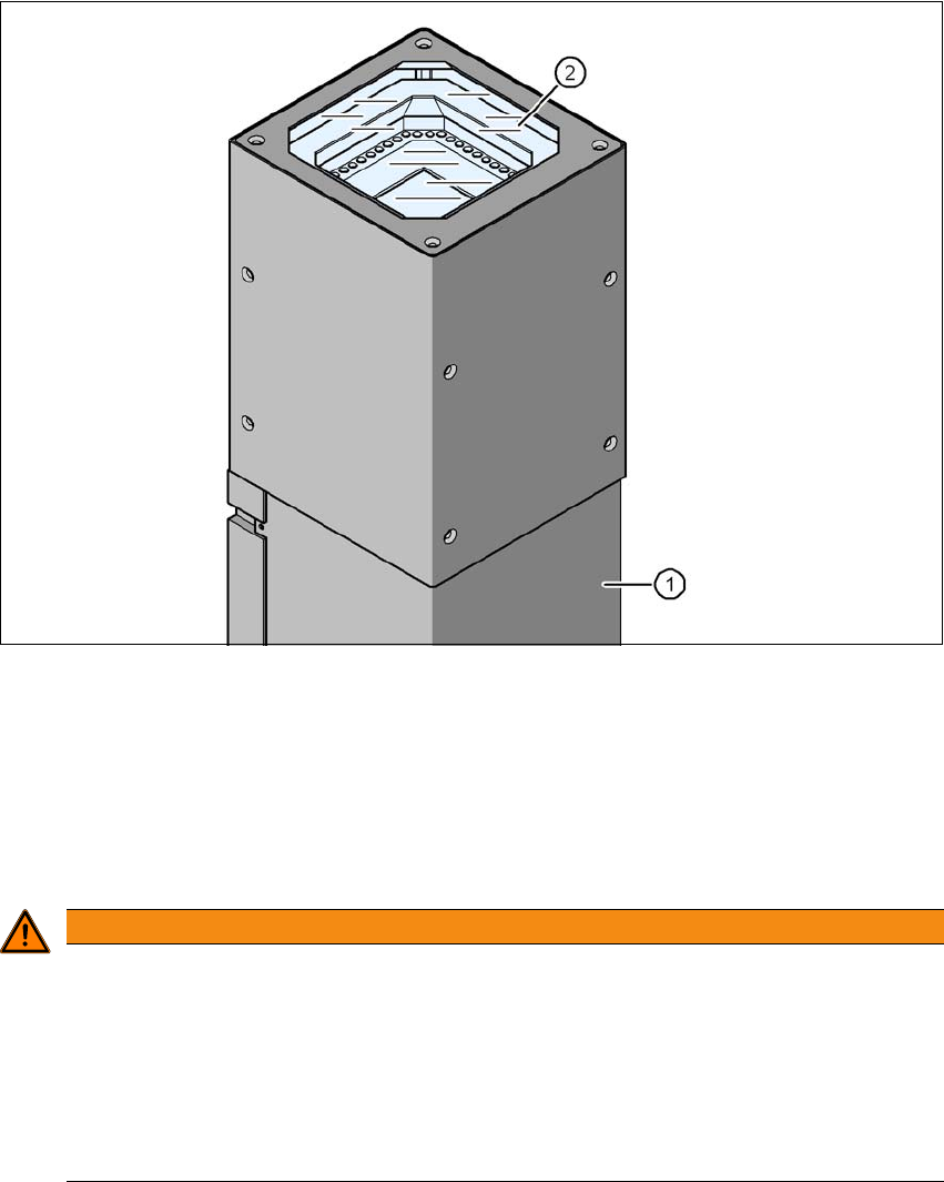
6.11 Component camera for the TwinStar, FC camera
6.11.1 Stationary P&P component camera (type 25) 16 x 16, digital (FC camera)
Item no. 00119718-xx Stationary component camera 16x16 digital, type 25
6
Fig. 6.11 - 1 Stationary P&P component camera (type 25) 16 x 16, digital (FC camera)
(1) Camera housing with integral camera and camera amplifier
(2) Glass plate - illumination and lens levels below
6.11.2 Safety instructions
6
WARNING
Risk of collisions!
When changing the placement head from a TwinStar/VHF to a SpeedStar, the SpeedStar
collides with the camera housing.
Dismantle the stationary component cameras of type 33, 55 x 45, digital and type 25,
16 x 16 digital (FC camera) for the TwinStar.
When changing the placement head from TwinStar to MultiStar, the stationary component
camera, type 33, 55 x 45, digital, is fitted in the bottom position.